Subsections of K0EMT Amateur Radio

Subsections of Antenna Projects

900Mhz Antennas

928 5 element colinear

1" aluminum tubing was used for the large sections. 12 gauge stranded copper wire with ring connectors for the small wire sections. The ground plane wires are from brass rod. Ring connectors were soldered on to the brass rod. The rods were riveted to the base section of tubing. All stranded wires were riveted to the larger aluminum tubing. The coax used was Radiall-Larsen Dual shield RG-58.

Peformance is much better than the three quarter wave below. A station that had quite a bit of QSB on them with the 3/4 wave was Q5 with this antenna. With the SMA3 they could not be heard and they couldn't hear me either.

I really need to go back and rebuild this antenna. After revisiting Ross's site below, I realized that my first element is improperly built. I should be feeding the first fat element in the center. I also did not utilize the 75ohm quarter wave match that he does.

I built a similar 3 element colinear for VHF. I tried the techinque of feeding it through the bottom section to act as a decoupler trick and it doesn't appear to work all that great. I'm going to try it out again with a 75ohm quarter wave match.

This site was the inspiration for this antenna. I just sized things for 928Mhz.

928 3/4 wave

This antenna was built with all scrap box parts.

The top piece of aluminum tube was left over from an antenna trimming/conversion project. The bottom piece of tube was from scrap that was cut off of another antenna. The RG-58 a/u with molded BNC was another piece of scrap. As well as the PVC tub that serves as a support. The ends of the coax had ring connectors soldered on them. Both piece of aluminum tubing were drilled through the pvc support. Then the coax ends were connected to the aluminum tubing with aluminum rivets. (The tape is added for waterproofing and aesthetics.)

It performs better than the Comet SMA 3 it replaces.

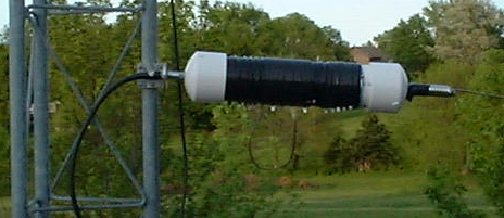
Base Loaded 160m Half-sloper antenna

big coil big coil

Zoom in on taps

I wanted to have a resonant antenna on 160M so this is what I came up with.

Materials

  • 3in PVC tube
  • PVC Caps
  • Mirror Mount Bracket
  • Spring
  • ~66ft of Flex-weave wire
  • 12awg solid copper wire
  • Spade type connectors
  • PVC cement
  • Miscellaneous hardware

Construction is pretty straight forward

  • Drill end caps for 3/8-24 hardware
  • Ring connector on end of wire that was fed through PVC tube for cap.
  • wrap wire around coil form. Every so often place a tap (spade connector). Closely wind wire and wide space taps for big jumps in inductance. Closely tap wire and increase space on winding for small jumps in inductance.
  • finish off wire with ring connector and assemble last end connector.
  • Drill very small “breather” hole in one end cap
  • Put female connectors on a length of wire that will be your jumper.

Notes

  • I used this on the mobile with a small mast and 56in whip for 80m.
  • Sometimes when I’m really motivated I will solder all taps
  • coil is wrapped in tape to keep it from shifting.
  • spacing between wire affects amount of inductance
  • spring on end cap was used to provide some give for wire
  • 1:1 VSWR at 1.9Mhz. 9:1 at both ends of the band
  • If you can find end caps that are squared off and flat instead of rounded you will make things easier on yourself.

F-150 Mobile QTH

k0emt's F-150 Mobile QTH
6m/2m Home Brew Whip

k0emt's 6m/2m whip

The mount is a split ball type. I used several different brands to get the combination of insulator type/color and ball material that I wanted.

I used a completely threaded 3/8"x24 TPI bolt with an Allen style head and a lock washer for mounting the cobalt steel heavy duty spring to the mount.

Next is a lock washer and a medium duty stainless steel spring.

Then a 3/8" x 3" extender topped with a barrel connector with locking nut.

A whip adapter with stainless steel whip tops it all off.

The radios in my truck are mounted on a "Shelf-it" brand over head shelf. I went with this brand because the fabric covering is actually fabric particles that are blown on to an adhesive coated aluminum shelf. (That way you don't rip all of the shelf material off when you are drilling holes!)
wider viewer of 6M 2M home brew whip

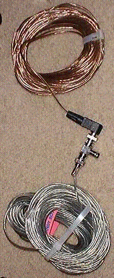
Field Expedient dipole for 80m

Summary

This is my 80M "field expedient" antenna. I primarily use this as a NVIS antenna with my FT-817 QRP rig.

Materials:

  • 16 Gauge Speaker Wire
  • Crimp style BNC connector
  • Radio Shack right angle "solderless" connector
  • F-F-F BNC T from Radio Shack
  • 2 16 Gauge Ring Terminals

Construction:

  1. Cut the zip cord a bit long (as usual) ~68 feet
  2. Pull it apart so you have each side of your dipole
  3. Strip and solder one end of each wire
  4. On the crimp style BNC connector
    1. Wrap the soldered end around the shield collar
    2. crimp it and solder it to ensure a good connection
      The center conductor will not be used on this connector!
  5. On the right angle connector
    1. Wrap the soldered end around the center conductor screw
    2. Tighten down the screw
    3. Solder it to ensure a good connection
    4. Make a right hand knot around the shield clamp to give a bit of strain relief
    5. Clamp the shield connector down around the insulated wire
  6. Connect them together with the FFF BNC T
  7. Connect to your rig/analyzer with appropriate coax
  8. Tune/prune to appropriate length
  9. Finish off ends of wire with ring terminals
    1. Strip a bit of insulation off of the wire
    2. Tin the end
    3. Crimp on the connector
    4. Solder the connector

Notes

  • Use "reuseable" zip ties to manage transport/storage of this antenna.
  • Pick up a piece of 10-base-T RG-58A/U "Networking" Coax with Male BNC's at each end while you're in Radio Shack. (Over with the computer stuff.)
  • Obtain two lengths of nylon cord of a size that will easily go through the eye of the ring connector. Used for tying off of trees, poles, etc.
  • The bag I use has two side pockets. One half of the dipole goes in each side.
  • With a small tuner such as the Emtech ZM-2 or LDG Z-11 you will most likely be able to work 80M-70cm with this antenna. (I found I could use the ft-817 on several bands as constructed.)
  • I am not affiliated with Radio Shack or any other retailer.
WA2ZKD suggested the following (edited):
  • The BNC connectors used are OK for on/near resonance and QRP operation. When used at higher power-off-resonance, like with an antenna transmatch, they may arc.
  • For NVIS, an electrically long dipole may not do as well as a dipole cut to frequency. This is because the long dipole may "lobe up" and show directionality.
  • The addition of a simple current balun, such as the W1JR with ferrite on the feed coax, will help and cost little.

Variations

  • On one vehicle I have a home-brew 1/4 wave whip for 6 meters. It is connected to the HF/6 port of an ICOM 706mkII. Disconnect one side of the dipole from the BNC T. Slip it's ring terminal over the mobile whip. Ensure a good mechanical contact. Throw the end with the BNC up in a tree. In some way support it so it's not in contact with ground. Now you can work 80Meters. I checked into the Missouri traffic net with this antenna and received 59 reports.
  • Install Anderson Power-pole connectors at the appropriate places in the wire so that you can make 80-6/2M dipoles. You will have to tape/support the connections in some fashion. If left un-taped/supported spade, bullet and anderson power pole connectors will come apart under tension. (I have emailed Anderson requesting that they manufacture a wrap of sorts that would provide strain relief and lock a single connector together. In the mean time perhaps an overhand knot will do the trick.)
  • Using a small machine bolt, pair of washers, lock washer and nut, connect the halves together at the ring connectors. Plug end with center conductor into rig/tuner for a 160M 1/4 wave. (Do something with the rig's ground connector for this configuration!)

Reports from Builders

  • KC0IFL reports that he built this antenna for 20 Meters. He succesfully used it with his K2 and ATU in an inverted L position from a second floor hotel room.
Picture of 80M Field Expedient Dipole
72/73 de k0emt

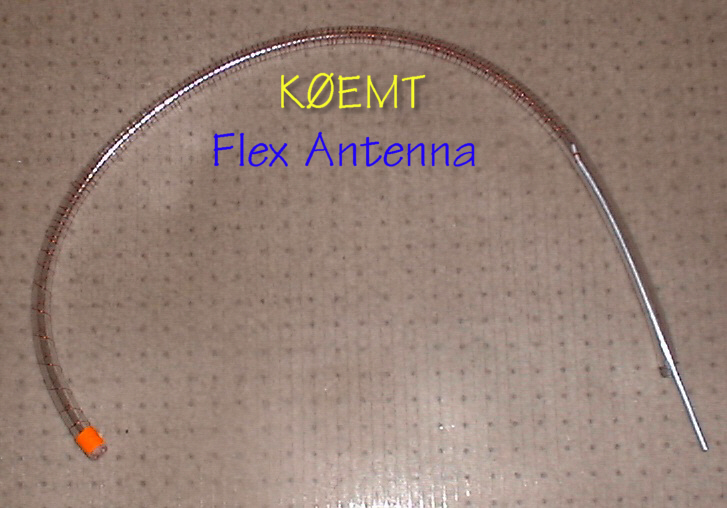
Flex Antenna


Numerous people on several yahoogroups, of which I am a member,
have commented about the need for a flexible HF antenna.
This is a prototype antenna I built up from material on hand.

    Materials
  • 3/8" outer diameter Vinyl tubing
  • aluminum grounding wire
  • copper wire
    Construction
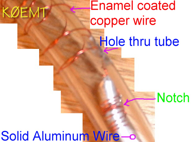
  • Cut a 6" length of aluminum wire
  • Cut a hole big enough for the wire to pass through in the tubing. It should be about 4" from the end.
  • Using your cutters put a notch in aluminum wire very near the end.
  • Tie your copper wire to the aluminum wire. It will slip up into the notch.
  • Solder the wire to keep it from slipping.
  • Feed the aluminum wire through the hole you cut.
  • Wrap the vinyl tube with the copper wire.
    You may want to insert a rod of some sort into the tube to make it easier to wind the wire.
  • Secure the end of the copper wire with tape.
  • Trim Vinyl tubing and aluminum wire to fit into appropriate antenna base. (I suggest 3/8" x 24TPI whip tip adapter.)
  • Evaluate on antenna analyzer
  • Have fun!

The antenna shown has approximately 20" of tubing.
The analyzer says it is resonant on 6M and 70cm.
On the air tests with the Yaesu FT-817 show this to be true in operating as well.

Variation: use a section of 3/8" x 24TPI bolt instead of the aluminum wire. Warm the vinyl so you can work the bolt head into the tubing. Use a ring connector on the wire at the bolt end. Tape the wire to the tubing around the bolt head to help secure everything.


HF Receive Antenna

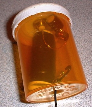
If you are only using the stock antenna that came with your SWL radio, Yaesu VX-7 or Kenwood TH-F6/TH-F7 you are missing out on a lot. This page describes a couple of parts box medicine bottle antennas that you can build. Specific values are not that important. Especially for receive only use.

In one example the coil was wound on 3/8" plastic tubing. In the big bottle example the coil was wound on ~1/2" plastic tubing.

The ground side of the capacitor is soldered to the ground of the BNC connector. The positive side of the capacitor takes 5 turns around the toroid and is soldered back to itself. The center pin of the BNC connector takes 5 turns around the toroid and then continues on to the wire wound inductor. From there the antenna continues with an attached piece of wire.

Toroid, capacitor and inductor specifics are not critical as this is intended primarily as a receive antenna. You can check your resonant frequency with a tool like the MFJ-269. This simple antenna will greatly increase your enjoyment of HF SWL with your TH-F6a.

Give this simple parts box antenna and matching unit a try and you'll be surprised. I'm only using about 6Ft of wire after the inductor. For the larger coils I used a plastic form and ~22AWG magnet wire. For the smaller coil I used a piece of tubing used on water systems with very fine magnet wire. Materials and values are NOT critical for the most part. The Important thing is to have fun!

Frequently Asked Questions

  1. What diameter should be the of the wire winding on the core of a plastic tube?
    22 awg the inductor. I believe I used larger for the toroid. This is enamel coated wire.
  2. On the steps which wire has to be wound on the first core inductor, for how long and what section of the pipe has to be the best on the tube diameter wound wire will also be useful to know the total length of the wire?
    The center + side of coax takes 5 turns around the core and continues on to the inductor. The ground - side of the coax goes to the capacitor. From the capacitor it takes 5 turns around the core and folds back on itself. The picture at http://www.dbbear.com/k0emt/projant/hf_rcv/mb_core2.jpg probably shows this the best. For the tubing you can use a small piece of pen or tube like you find in a water bottle straw. There is very little length of wire around the toroid.
  3. At which length of the section, the wire has to be wound on the second inductor tightly wound core, same tube of the same diameter?
    The only reason I had a gap in the winding is because that is the way it turned out. No technical reason.
  4. What value should be 1000uF capacitor in volts, I see the picture that it has 1000uF and 85 degree Celsius?
    Again, try with whatever part you have handy. The one I used was 6.3V.
  5. What diameter of wire wound on a core of green ferrite has to be, and its length?
    This wire looks to be about 22AWG and was very little on toroid, about 2M on coil form.
  6. How diameter of the copper wire must be wound on the ferrite core, and its length?
    I believe this wire is 18AWG and very short. It is also enamel coated.
  7. What must be the diameter of the external and internal ferrite core and what its height?
    Not critical. The one I used: ~4mm tall, OD ~12mm, ID ~7mm.

The biggest thing is to have fun and experiment.

Drop me a line and let me know how it works for you.

Pedestrian mobile HF/VHF backpack

Back view of backpack with antennas

Counterpoise Length

How long is the counterpoise? The overall length including the "pigtail" that is attached to the antenna bracket is the appropriate length for the frequency based on Bonnie KQ6XA's research. Here are some excerpts from the Counterpoise_Radial_Length file provided by the HFPack group.

Counterpoise wire touching Earth

The problem of predicting or computing the length of a resonant wire gets more complex when using dragging counterpoises and very low radials or radial wires laying partly on the ground. Because of proximity to the earth surface, the wire needs to be shorter. Earth (soil) conductivity affects the resonance, so different soil types may require different length counterpoises. Generally, the more conductive the soil, the shorter the counterpoise.

Pedestrian dragging counterpoise length With broadly tunable whips (such as MP-1, mobile whips, etc)

I've found empirically that a pedestrian dragging counterpoise wire can be about 10% to 25% shorter than the standard quarterwave formula predicts, and the whip will usually tune to a fairly good 50ohm match. Insulated wire with low ohmic resistance should be used. For best dragging quality, Teflon or slick PVC-jacketed or oil-resitant multistrand wire is best. For safety while walking with a dragging counterpoise, some sort of slip-connector or an alligator clip should be used so that the connection will break apart if the wire is caught by a rock or vegetation.

KQ6XA's dragging counterpoise length by band

  |BAND| FEET | 
  |----|------| 
  |10m | 7.4ft| 
  |12m | 8.0ft| 
  |15m | 9.9ft| 
  |17m |11.0ft|
  |20m |14.0ft|
  |30m |18.5ft|
  |40m |26.3ft|
  |60m |34.3ft|
  |75m |45.4ft|
  |80m |49.3ft|
  

Pictures

Backpack

I am using a bass pro big country pack. I picked this backpack for it's external frame, hydration pack and because it fit me! The frame and padding are set up really nice. They do a really good job of letting air circulate around. I was really surprised when I felt a breeze come across my back while wearing it.

Antenna Mounts

I found some great brackets at a truck stop for mounting antennas. They are Barjan 300-306, "GM Models" prior to 1990 Mirror Mount. I did grind down the part of the bracket near to the pack.

One mount is configured with NMO so I have a lot of versatility with it. Using adapters can go to UHF or BNC F. Coax is terminated with BNC.

The other mount is standard 3/8-24 with a quick-detach stud. Connected a detachable counterpoise wire to one of the nuts on the mount.

VHF/UHF Station

I use a Kenwood TH-F6a mated with a Comet SBB-5 dual band antenna. The rig was an easy choice. The main factors were simultaneous dual VFO's, all-MODE recieve and excellent battery life. I can keep one VFO on a local repeater or simplex frequency. The other VFO can be monitoring 18.157.5 USB. So, then I don't drain the HF rig's battery in RX.

The antenna was a tough choice. In the end I went with a Comet SBB-5 because I like the black color with the pack, the height is just right, flexibility is good and I had one on hand. Why do I care about height for this antenna? As you wear the pack it is on the right side. I did this because typically a brush/trees that hang over the trail are lower on the outside. I'm going to see how this works out, but I will be very tempted to get one of the new Comet EX-510B NMO 6/2/440 antennas. It doesn't take much additional antenna on the F6a to really bring up the receive on HF.

HF Station

The Yaesu FT-817 is the rig that I use on the HF/50 side of the house. I use the homebrew vertical for the antenna.

  • Use the whip only for 6/2M operation ~55 inches.
  • Whip w/coil for 10m, 12m, 15m, 17m, 20m, 30m & 40M.
  • With the 9ft whip, 80M
  • With the 6 Meter whip and all of the coil bypassed the antenna is resonate in 10M band.
  • With all coil in good to 4.2Mhz.
  • With 9ft whip, good below 80M.

Antenna Construction

  • I used 1 1/2" PVC for the coil form. Female Spade QD's for the taps.
  • 16 gauge wire
  • didn't calculate taps, evenly spaced at 10 turns.
  • Bottom of coil has 10 turns that are tapped at every turn, use this as "fine tuning" section.
  • Below fine tuning section is 3 turns.
  • The coil itself is right at 12". This means that there is a little bit of empty space after the coil then the caps.
  • Use vertical drill press to make holes for 3/8-24 TPI bolts in the flat end caps. Use lock washer and washer on inside of cap.
  • End caps were glued on. Then riveted. PVC is a soft material so it is not unusual for the rivets to want to pull through.

Counterpoise

I have a length of 14 gauge wire that has ring connector on one end and a female spade connector on the other. The ring connector is attached to the antenna bracket. The wire is routed down around the outside of the pack to where it terminates in the female spade connector. I then attach a counterpoise wire that has a male spade connector on the end. With this arrangement if the counterpoise gets hung up on something, it disconnects. Otherwise, the wire could pull on you causing you to lose your balance and fall. Not a good thing.

Now, the question becomes where to put the quick disconnect? Because of the way I have my wire routed I opted to put it a couple feet away from the bracket, past the end of the pack. My thought is to put the quick disconnect far enough out that you can easily reach back, grab the wire, pull the connector around in front of you and plug the dragging part back in. Saves you from having to take the pack off or from practicing to be a contortionist.

Also, take a piece of flagging tape and tie it to the part of the dragging counterpoise that is by the quick disconnect. Now when it comes unplugged you'll be able to quickly spot it. Optionally, use a brightly colored wire. But be prepared to have LOTS of people tell you, "you're dragging a wire."

Identification and Patriotism

I've also added a yellow ribbon (HFPack identification) to the VHF/UHF antenna. The yellow ribbon is also a traditional indicator of support for our troops. Thin, ribbed cloth type, melted the ends to keep from fraying.

On my HF antenna I added a US flag to the top. I used a flag that came on a round tube. Cut the top off the tube and again below the flag. Secured to the whip by putting zip-ties in place above and below the flag. HINT: wrap the zip tie twice and through itself to really snug it up! Now the flag waves freely when /PM.

Safety

When in an urban environment the ribbon and flag also serve as added visual attention getters. Especially handy when you're in hilly terrain. I sometimes find myself out during the twilight hours. For those times I have an LED flasher on the back of the pack. I also keep an LED flashlight in one of the pack pockets. Plan your route, follow your route, and make sure someone knows you're route and expected times. Pretty much your standard hiking/backpacking safety rules apply.

Be safe and have fun! 73 -- de Bryan, K0EMT

QRP Lowfer

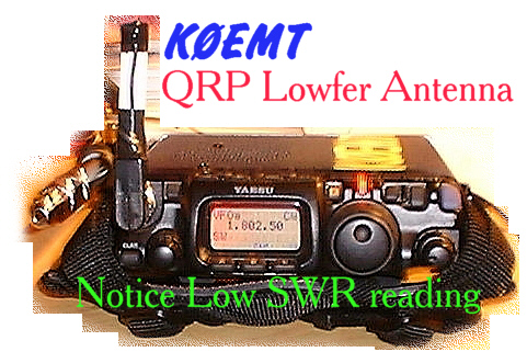
K0EMT's QRP Lowfer Antenna
The lowfer "kit" - a bit fuzzy SRI!
Close Up - very sharp!

Numerous people on several yahoogroups, of which I am a member,
have commented about portable HF antennas being a compromise in
performance versus convenience. I believe this antenna slams down
the scale on the side of convenience for operating 160M and 80M portable.

Materials

  • Right Angle BNC Connector
  • Radio Shack #271-133 - 50Ohm 10W Resistor

Construction

  • Solder one wire of the resistor to the ground side of the BNC
    Check for clearance with Plastic boot first!
  • Solder a jumper wire between the other wire and the center conductor of the BNC
  • Replace plastic boot and Vinyl tape boot and exposed wire.
  • Evaluate on antenna analyzer
  • Have fun!

The analyzer showed low SWR on 160M and 80M. My FT-817 agrees.
40M and 30M show a bit higher SWR on the analyzer.
The 817 shows 3 and 4 bars respectively.
I was testing with 2.5W out CW.

Rigid Dipoles

I have been playing with PVC and Aluminum Tubing for building rigid dipoles.

Most have been built for 10M, 6M and 2M. With the idea of portable operation.

There is a picture of a center "T" with BNC from one of these smaller antennas.

There are also a number of pictures of a 20M dipole here.
For this antenna, a coax "pig-tail" was connected to the interior bolts on the center T.
You will note the larger hole. This is so that a metal nut can tighten the assembly at this point
while providing a good physical and electrical connection to the antenna.

It is full-size, no loading. The antenna is in operation at the QTH of KB0HNR.

It is a top his 45ft tower.

Much to my surprise it has weathered severe storms with winds in excess of 60mph.

I hope that these pictures will help you in your construction projects.

Smaller rigid dipole
K0EMT with 20M Rigid Dipole 20M Rigid Dipole details

Side Mount VHF/UHF Antenna

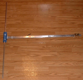
This antenna is designed to be mounted off the side of a tower. The idea is to run the arm through the tower, bracketing to the far side of the tower. The middle of the arm should be zip tied to the tower.

In the "laboratory" this antenna showed a VSWR of <= 2.0:1 from 136-153.1Mhz. With 1.1:1 at 144.2. This is good since the primary intent is to use it as a packet antenna. It also tested well for the entire 70cm band.

Materials
  • Left over arm from scrapped CB antenna
  • Left over element from converting Radio Shack FM antenna to 5el 2M beam
  • Left over piece of dual-shield RG-58 coax
  • Female BNC
  • Mast mount bracket
Construction
  • Polished arm, restoring appearance to near new
  • Trimmed length of arm and installed mount bracket
  • Drilled arm to accept a rivet through the element
  • Riveted element to arm
  • Installed ring connectors and Female BNC on coax
  • Made several loops of coax to form balun
Pictures

By the way, I will be going to black UV resistant ties before installing permanently.

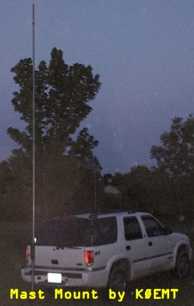
Trailer hitch mast mount

K0EMT's Mobile Antenna Mast Mount

I designed this this mast mount because I wanted to be able to rapidly deploy a mast mounted antenna in a location that didn't have other supports available.

    Design Criteria:
  • When not in use fit inside vehicle
  • Be able to handle large to small diameter masts
  • One person should be able to safely put up mast
  • Should not require user to lift mast through top clamp
  • Even if collar is loosened, it shouldn't slide down mast
  • Should be a no-tools deployment
  • Minimize moving parts
  • Can open window portion of hatch while mount is in place
    To deploy this mast mount:
  • Put the bottom collar on the mount first
  • Secure the mount in the hitch
  • Make sure the bolts are loose on the bottom collar
  • Put your antenna on the mast, pulley for wire support, etc.
  • Slide the top collar onto the mast
  • Place the end of mast on top of the bottom collar
  • Hold the smooth side of the collar in your hand, supporting the mast
  • Support the mast with your other hand as well.
  • Erect the mast keeping the bottom in the mast mount
  • As you get near vertical the mast should drop to the ground inside the bottom collar
  • Slide the top collar down into it's tab, making sure to orient it properly.
  • Tighten down the top collar
  • Tighten down the bottom collar
  • Done!

After having practiced with this mast mount, I would likely have the bottom collar welded to the rest of the frame. Although that doesn't lend itself well to transport. So, it's a toss up.

John, AA0ZC built the mount for me. If you would like him to build one for you, contact him directly for an estimate.

VHF/HF Mobile Antenna by K0EMT

  • Use the whip only for 6/2M operation
  • Whip w/mast & coil for 10m, 12m, 15m, 17m, 20m, 30m & 40M
  • 80M w/wire attached to QD mount
* End Cap & Mast
** Generation 1
   Bottom has a 3/8" x 24TPI bolt in a PVC end cap.
   Then a section of 1" aluminuum tubing.
   Overall length and coil weight of the Gen 1 have relegated
     it to a primarily portable HF vertical role.

** Generation 2 
   Changed to a metal end cap, filling in extra space with PC-Metal Epoxy.
   Then a section of 1" aluminuum tubing.
   Mast shortened for mobile operation.

** Generation 3 
   Copper tubing mast design.  Much nicer appearance.
   Field use demonstrated that the copper is too weak for extended use.

** Generation 4
   Fiberglass tube w/epoxy filled PVC cap

* Coil
  A smaller section of PVC slides inside of the mast.
  Coil is wound on the PVC.  

** Generation 1
   Topped off with another bolt that has been pressed and epoxied into
   the PVC tube.   Then a whip tip adapter and a whip.
   Taps at various places, required tuner.
   Antenna ends up ~9'9" tall.  With full coil resonant at ~6.9Mhz.
   Bypassing coil it covers the entire 10M band &lt; 1.8:1.

** Generation 2
   The bolt is simply put into the PVC end cap.
   Nut and whip tip adapter arrangement.
   Taps are located for resonant frequency, no tuner required.
   Coil shortened for better mobile operation, only goes to ~10Mhz now.

** Generation 3
   Nut and whip tip adapter configured with Quick Detach spade connectors.
   After 20M tap switch to smaller gauge wire, allows for 40M operation.

** Generation 4
   In progress, going to fiberglass coil form.
   Most likely will use PowerPole connectors instead of spade connectors.

* QSO's
First Contact, Generation 1
05 Feb 02 1035 CDT 28Mhz EA3XA 58 58 Jose - Barcelona Spain
			 w/ICOM IC-706 mk II @ 100 Watts

* 80M
Use a wire with Max Coil for 80M, works well for Section Traffic Net.
Better results on 80M can be obtained by using a 56" extender 
below the coil.  (Stationary use only!)

* Costs
Al Tube ~$4 (~$12 for 8ft pc)
PVC Tube $1
Wire ~$4
Incidentals - Epoxy, Hardware, Ring Connectors, tape ~$2
3/8" Hardware - ~$7
Whip - ~$7
Total ~$25

10 Bands for about the price of 2 mobile monobanders.

* To Be Done
** Document
Where tapped, how chose where to tap.
How tapped, 14Gauge wire
length of each section

X-Beam Antenna

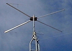
K0EMT VHF/UHF/HF? X-Beam Antenna
VHF/UHF X-Beam Construction Notes (and HF see update below) -- k0emt

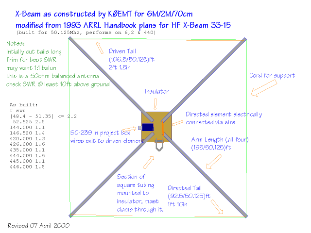
I sat down and drew out what I did and thought I'd pass on what I did/found out. The design is from The 1993 ARRL handbook that was given to me by wd0hbx. The x-beam was originally intended as an HF mono-band beam. I used the formulas to build it for 6m. It also happens to work out really well for 2m & 70cm use as well.

The text says that this antenna design will typically have a 6-8dB gain and a forward to back ratio of 20dB. The handbook also states that this design should perform as well as or better than a similar yagi.

Notes:
(That will make more sense when you look at a picture.)
There are tails on all four arms.
I didn't have my arms exactly perpendicular.
I had the inside angle of the directed element < 90 degrees.
I used square tubing on the back and round on the front.
Tie the tails to the nylon cord that is strung around the beam for support.

f       swr
(48.4 - 51.35) <= 2.2
50.110  2.2         420.000 1.3
50.125  2.2         426.000 1.6
52.525  2.5         430.750 1.6
                    435.000 1.1
144.000 1.1         436.300 1.6
145.050 1.2         442.000 2.0
146.000 1.3         444.000 1.6
146.400 1.4         445.000 1.1
146.520 1.4         446.000 1.5
148.000 1.2
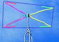
Green Directed Tails Wire
Yellow Directed Arms Tubing
(Wired together at vertex)
Cyan Project box SO-239
(Wires lead from here to driven elements)
Purple Driven Arms Tubing
Red Driven Tails Wire
Blue Support Cord Nylon Cord
Runs around perimeter
zip tie wire tails to this support
also used to provide stability

On air testing has shown that it is indeed directional. Had S-8 noise on discone, switched to beam, now S-3. Conversely, when testing on 6M with a horizontally polarized "local" station kb0qhz, noted an improvement of 5 S-units when using beam. (cross polarization could come in to play though -- the discone is vertical.)

When testing with kb0hnr mobile in Jefferson City, MO I was able to copy him at times S5-9 when the discone couldn't even hear him. A similar gain was noted when hearing DX when cross-polarization shouldn't be an issue.

Noted, that when I changed the direction it is pointed wasn't able to bring up certain local 2M FM repeaters.

Hooked up an ICOM 706mkII, using 20w on 2M SSB made a contact with K9IMX (Lake of the Ozarks), he reported me 57. He regulary works n9wyx, another "serious" 2M ssb station within ~1/2 mile of my QTH and he said he was impressed with my signal.

As a side effect, it seems like the discone is peforming better now than before. The discone is mounted off the top of a 20' mast. The beam is approximately one foot under it. Maybe, it's benefitting from some sort of ground plane effect?

Overall, I'm fairly happy with this beam. I have the feeling I will be building another one this year. I'll use better materials and be more exacting on the next go around.

If anyone decides to build one, please let me know. I'd be glad to help any way that I can and to stick it on the analyzer when you've finished construction.

2001 Jan 23 *******

kb0hnr was over recently. We had the antenna hooked up to my Kenwood TS-570S. The 570's tuner matched the rig to the antenna on 20 and 40 meters. We had a 59 contact into MA on 20m and were able to check into the 3905 net on 40 meters.

Not bad for a VHF/UHF antenna!

2001 May 31 ******

I now think that the reason the antenna was working on the HF bands was because it was so close to ground that there were some very strange interactions going on. The antenna was on a ground mounted 5ft Rohn tripod, with a 5ft Radio Shack Mast, Rotor & 4ft PVC mast attaching to the antenna. 2M and 440 were exhibiting good SWR but I was having a heck of a time with 6M. 6M would however tune.

Presently, I have moved the antenna a top a ~25ft Rohn 25G tower. As currently configured I have a 1.1swr for 144.2 and a 1.8swr for 432.1. 50.125 is currently showing a swr of 8.3, Rs=8 and Xs=17. Just this last weekend I added a 10' section to the tower increasing it to 25ft. I believe before I had done this that my swr was < 2.0 on 6M and on 2M,440 it was >1.5 but <3.0. I am coming to the conclusion that this antenna is very sensitive to it's height above ground.

For now, I plan to leave it as is, (I don't climb), and use the internal tuner of the TS-570S to make up the difference. Which it does just fine. By summers end I hope to add another two sections to the tower and a hazer. At that point in time I will try to adjust the antenna or make a matching circuit.

As an aside, the 570 will now tune the beam for 10M.

2001 October 09 ******

Beam is now at ~50ft. It is performing well.
Frequency and corresponding SWR as measured with MFJ antenna analyzer.

Freq SWR
21.450 2.6
21.3-- 2.8
21.0-- 3.3
18.168 2.7
18.068 2.6
14.350 1.8
14.225 1.9
14.150 1.9
14.025 1.8
10.15- 1.5
10.1-- 1.7
7.3-- 5.5
7.225 6.2
7.150 6.8
7.0-- 8.2
4.0-- 8.4
3.85- 9.5
3.75- 10.5
3.5-- 25.5
Freq SWR
446.0-- 2.0
432.1-- 1.4
148.0-- 2.5
147.0-- 2.0
146.0-- 1.6
145.0-- 1.5
144.2-- 1.3
54.0-- 1.4
53.0-- 1.6
52.525 2.2
51.0-- 3.2
50.125 3.4
29.6-- 3.7
28.885 4.6
28.5-- 6.0
28.3-- 6.6
28.0-- 7.5
24.99- 4.3
24.93- 4.1
24.89- 3.9

I could not get my Kenwood TS-570SG to force feed the X-Beam on 28.337. It did match it on 29.6. The rig will also not make the match on 40 Meters. Obviously it won't make the match on 80 or 160 either.

2003 April 03 ******

It is VERY important that the arms be of a significantly larger diameter than the tails. More info on specifics can be found at LB's (W4RNL) page below.

Here are some additional web resources for your perusal.
73,

Bryan - k0emt

Subsections of Equipment

Thoughts for HF/VHF Truck/SUV mobile operation

Tuner

The LDG RT-11 from LDG Electronics seems to be the best value.

Mounts

For mounting a whip antenna, split ball mount behind the drivers side of the cab, on the cab. Watch the height of this location. In the US, max legal height is 13ft 6in for most places.

My experience with springs is that they are more trouble than they are worth. (I’ve tried lots of ’em.)

Definitely go with a quick disconnect for the antenna mount. Not all QD’s are created equal. I like the one’s I’ve been buying from wb0w.

Also, not all split balls are created equal. You will want something like one of the Hustler heavy duty models. You can get ’em with either UHF or terminal connections on the back side of the ball. Another nice feature of these is that the plastic insulator has a crown of sorts on it, that helps to keep the mount from rotating.

An alternate mounting location and much stronger, would be to get a sheet of metal, cut it off into a triangle and mount it near the corner of the bed. This mounting location would be sturdy enough to support the biggest of antennas.

In any mounting location, make sure you have a good ground. I use a dremel tool with grinding bit to get to bare metal.

Antennas

Screw driver will work great and be expensive, but you won’t need the tuner.

You could use a CB whip as an ultimate compromise vertical.

If you get a set of “hamstick” type antennas with QD connectors you can use each one +/- 1 band. Use 15M on 17M and 12M w/tuner.

Or you could home brew a vertical solution for ~$35. My HB antenna lets me do 2/6M or any band 10M-30M while mobile. I can do 80M stationary with the addition of a ~40’ wire. I am working on a solution for 40M mobile.

Btw, I hope you had the RF filter installed in the fuel pump.

If you couldn’t tell, I love mobiling.

Also, if you give it some advance thought you could configure things so that you could easily transition it all to a back pack with battery, counterpoise wires, spare coax, etc.
Here is where the LDG Z11 and whips with QD connectors have an advantage.

73 DE Bryan, k0emt

Tips for new FT-818 owner

I am a huge fan of the Yaesu FT-817/818 radios. My first brand new HF rig ever was a FT-817 not too long after their initial release. I took it on many portable, SOTA, and POTA adventures. It had both the W4RT CW filter installed and the compressor kit in the microphone. That is the only rig I’ve ever regretted trading off.

Now I have a couple of FT-818s with different configurations. One more fancy, bells and whistles, the other more budget oriented. Both tons of fun!

2021 update

Yahoo groups are a thing of the past. Look for a groups.io group or a FaceBook group.

Also, we’ve gone from the 817, to the 817ND, and now the 818.

Filters

W4RT has long since gone out of business and their filters and compressors are no longer available.

Crystal filters are difficult to obtain for CW.

SOTABeams sells a digital filter that someone with advanced building/soldering skills can add into the rig. They also have an external version.

SOTABeams also sells an external speach compressor that is plugged inline with the microphone.

Finals

The 817 series has finals that are sensitive to high SWR and leaving batteries in them on the shelf. I recall reading something about how the finals stage was still getting power to it even when turned off (soft switch).

Check your output. Odds are that you will at some point in time join the blown finals club. Luckily, the 818 finals board works throughout the 817 series and is available from Yaesu. Fortunately, it is not an overly expensive part.

Internal Battery

NiMh

The 817 series is a power pig and won’t last very long on 1500mAh batteries. If you insist, know that not all AA NiMh are the same. Look for those with a capacity over 2400mAh. The NiMh will have a larger form factor and you’ll have difficulty getting them into the AA tray. You will also not be able to charge the NiMh AAs in the tray without doing a modification. Overall, skip on the NiMh batteries.

Lithium Ion

The best/most practical interal battery approach is to pick up an internal 3000mAh LiIon battery kit from WindCamp.

18650

Check the 3D printing sites. There are some options for getting a 3S 18650 internal battery set up.

External Battery

Print, make, or buy a Yaesu DC connector to Anderson Power Pole adapter that secures to the back of the radio. Be aware that if you leave the DC plug in all the time that you’re rig will think you have external power all the time. This means that your backlit display will not turn off when set to Auto.

I personally acquired a Bioenno LiFePO4 3Ah battery and charger for use with this radio.

Protection

Visit PortableZero products. They have battery cases that include a nice one for the 3Ah Bioenno. It also mates well with the 817/818 series. PortableZero also makes a bracket/bail combo that protects the front of the 817/818 series. The bail feature nicely positions the display and controls for field ops.

Antenna

I typically used this with a wire antenna and tuner.

Otherwise, I have several vertical options including: BuddiSticks, SuperAntenna MP-1 variant, or GRA-7350T. I prefer to use an elevated radial with the vertical antennas. If that isn’t possible, then multiple ground wires.

Coax

My preferred portable coax these days is RG-316. Start with what you’ve got. RG-58 is fine, but bulky and heavy. UG-174 is lossy and fragile. RG-316 is flexible, resilient, low loss and more expensive.

Tuners

When using a random wire antenna, you need to bring a tuner into the mix.

Elecraft T1

I built and use an Elecraft T1 with the 818. Add the control cable for some automated band switching. Not an inexpensive setup, but compact and very functional. Uses an internal 9V battery.

LDG Z817

Another great option is to use the LDG Z817. Fits perfectly on top of the 818. Can be bungee cord attached to the portable zero rails. Connects with a control cable. Uses internal AA batteries.

ZM-4

Awesome Z-match manual tuner kit that is no longer available. Works 160m to 10m. Balanced or unbalanced antennas. Slim profile. Fits right on top of rig. No batteries needed.

Keyer and Paddle

This rig does not have a built in memory keyer. When I want that feature, I find an ultra-pico keyer is a great add on.

For keying the rig, I typically use an N0SA paddle with 3M Dual Lock on the bottom of the paddle. That can in turn be affixed to a weighted base (or jeweler’s bench). My logging clipboard also sports dual lock.

Linear Amplifier

Check out PCBHobby and their HardRock 50 for a kit to build a 160m-6m 50-60w amplifier. There are options for an internal tuner and QSK operation. The 817/818 can be interfaced to the HR50 for band switching. This is a great addition for when you need more than QRP.

Yaesu FT-817 QRP Portable Station

This is an index to pictures of the Ambico bag model V-4420ASST. I use it for transporting my Yaesu FT-817 along with antennas and other accessories.
This bag is padded, has lots of zippered compartments and has a life-time warranty. I purchased it for less than $20 at Wal-Mart.

Since taking these pictures I have started using a Super Antennas 3/8"-24TPI mounting bracket. With this bracket on, the bag will NOT zip shut.

If you use the long whip and modified RS 11M back of set antenna, they can protrude from the same opening.

With everything that I stuff into the bag, including two extra sets of AA batteries, the bag weighs in at 10lbs.

June 2002

I have switched to UG-174 coax for quite a bit of weight and bulk savings. However, I do prefer the RG-58 when doing VHF+ weak signal stuff.

Also, Sears, a US department store, was clearing out some 35mm camera bags. I picked up one for $3 that a 7Ah SLA snugly fits into.
I put a fused pig tail on it with Anderson Power Poles. In the little front pouch I put the 817 barrel connector and PP pig tail and some spare fuses.
I threw in a couple higher rated fuses in case it needs to be used on another rig.

Pictures of the bag and contents:

Subsections of Kit Information

2024 EFHW Transformer

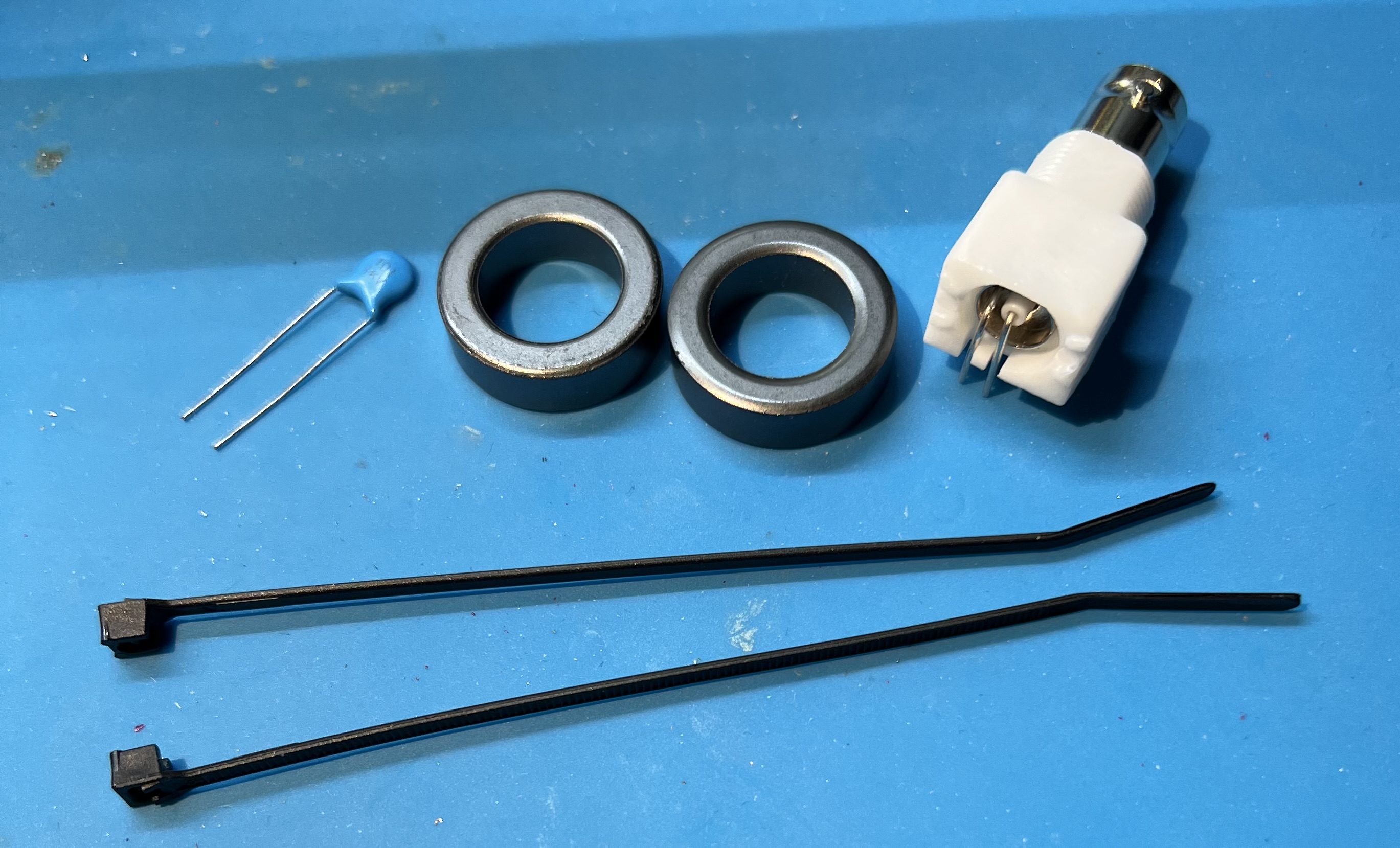
Components

  • 2024 EFHW Transformer board
  • 2 FT-84-43 toroids
  • 44" of 22AWG enamel coated wire
  • 1KV 100pF Capacitor
  • 2 zip ties

Tools

  • flush cutters
  • mini pliers
  • utility knife
  • ruler
  • soldering iron, set to 350C
  • ceramic tip reverse tweezers (optional)
  • spudger
  • heat safe work surface (or board holder)

Instructions

Resist the urge to follow the convention of installing small components first!

By delaying the placement of the capacitor we’ll be able to do some test checks and give ourselves some more room to work.

Subsections of 2024 EFHW Transformer

Double Stack

Winding

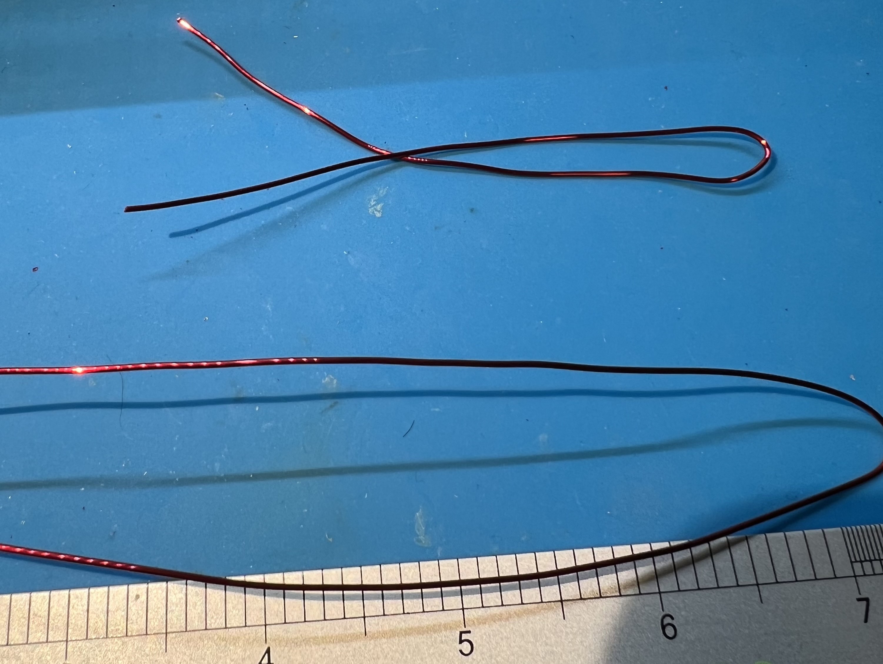
Use 20awg enamel coated wire. Primary uses 8" of wire, secondary uses 35" of wire.

The bare board. Bare Board Bare Board

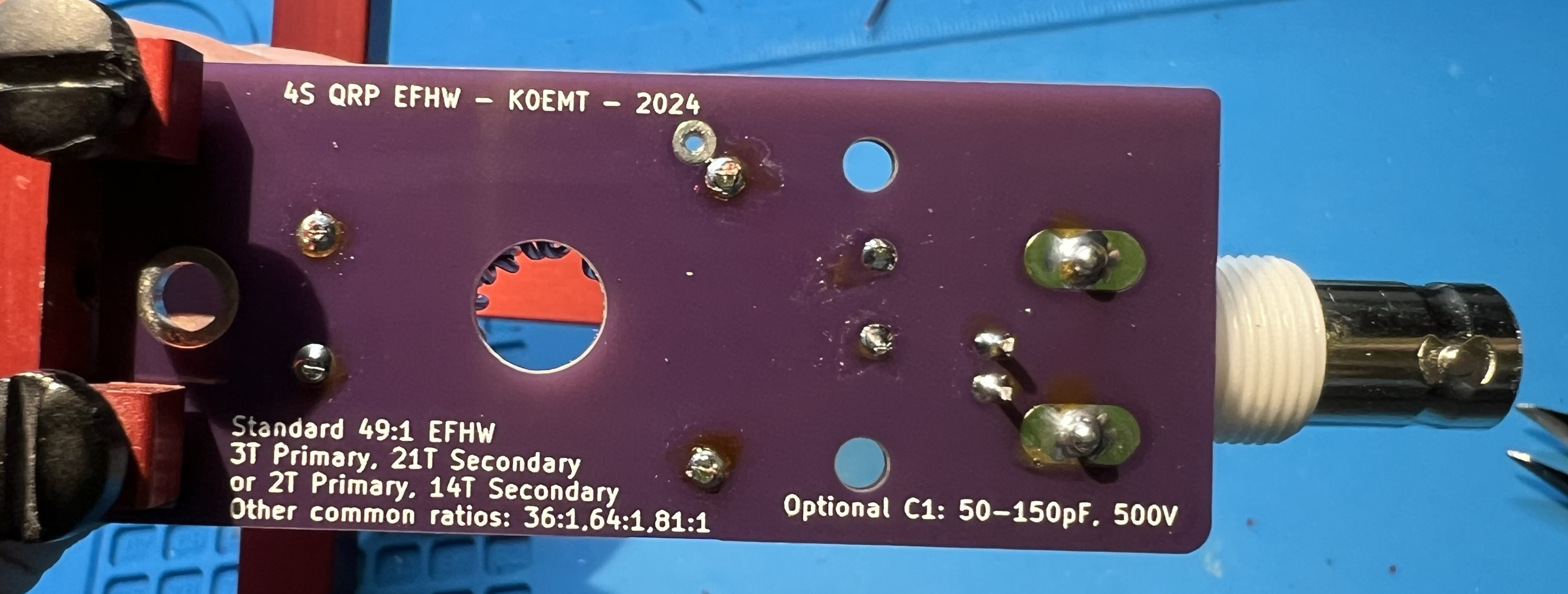
The capacitor, FT82-43 toroids, zip ties, and female BNC. Components Components

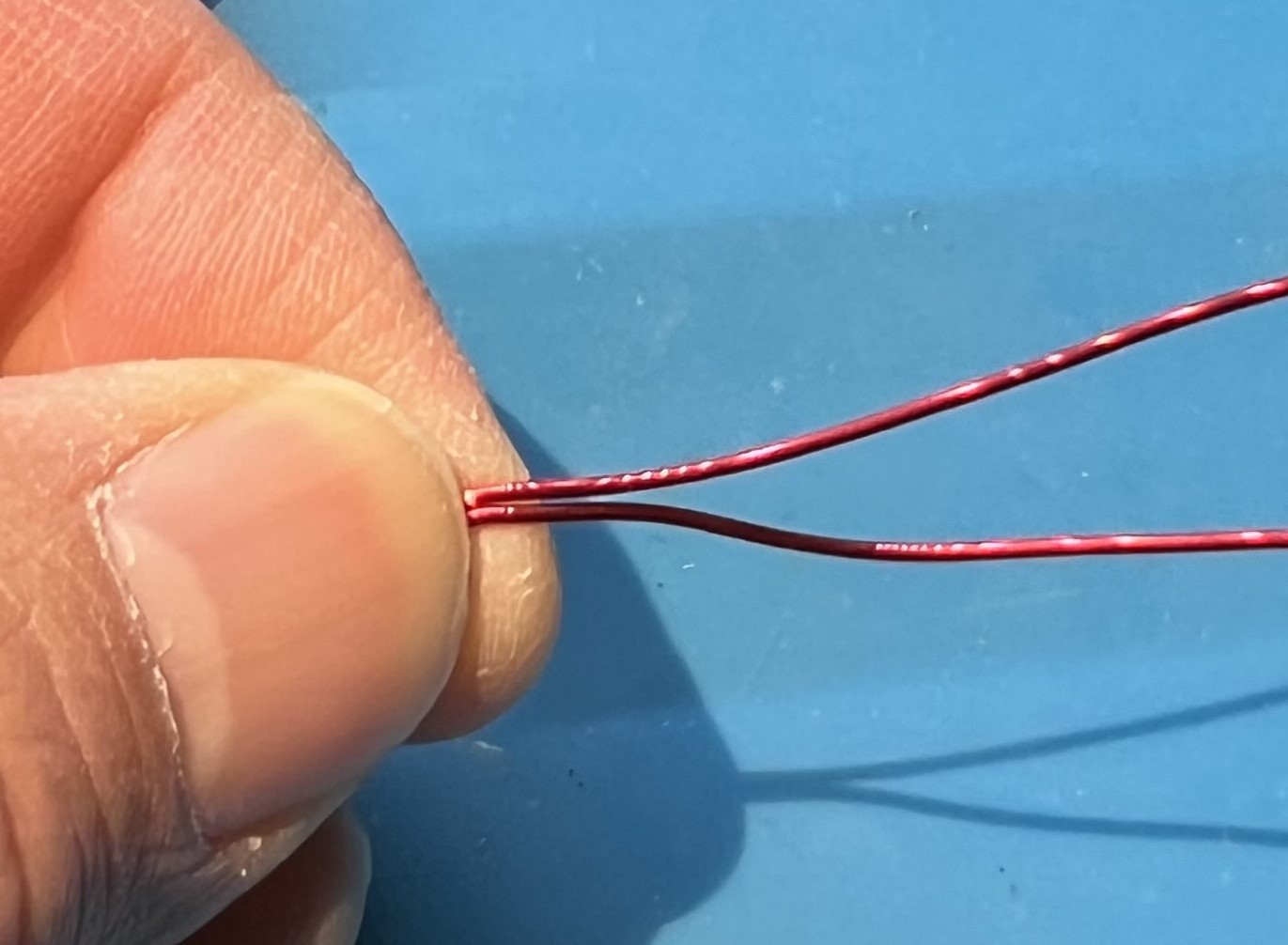
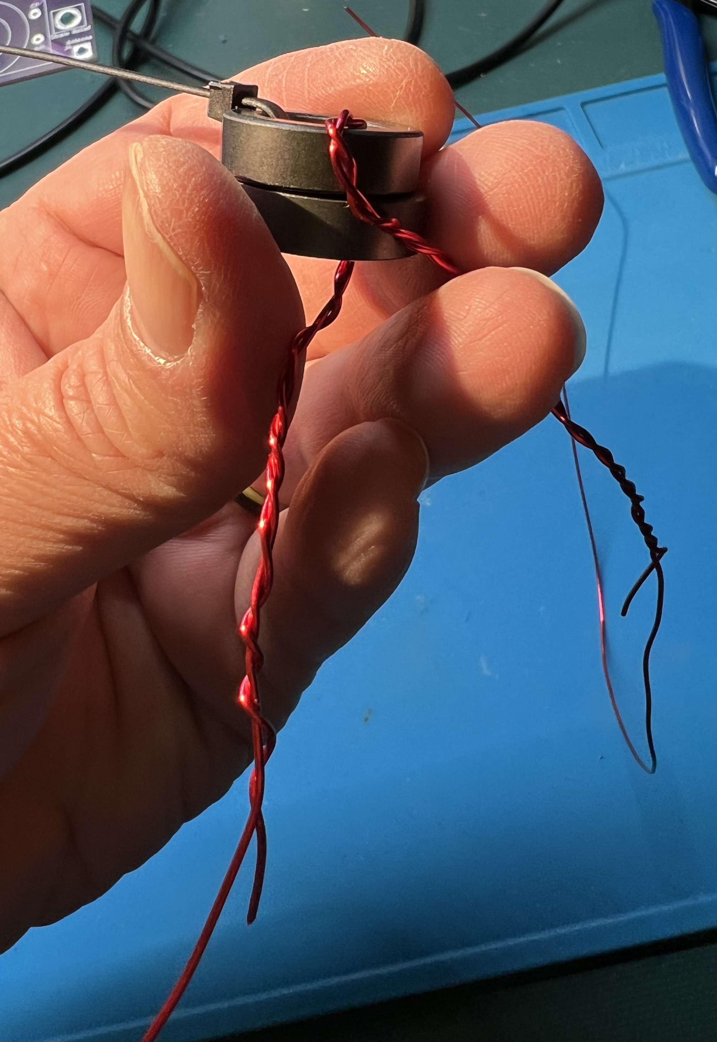
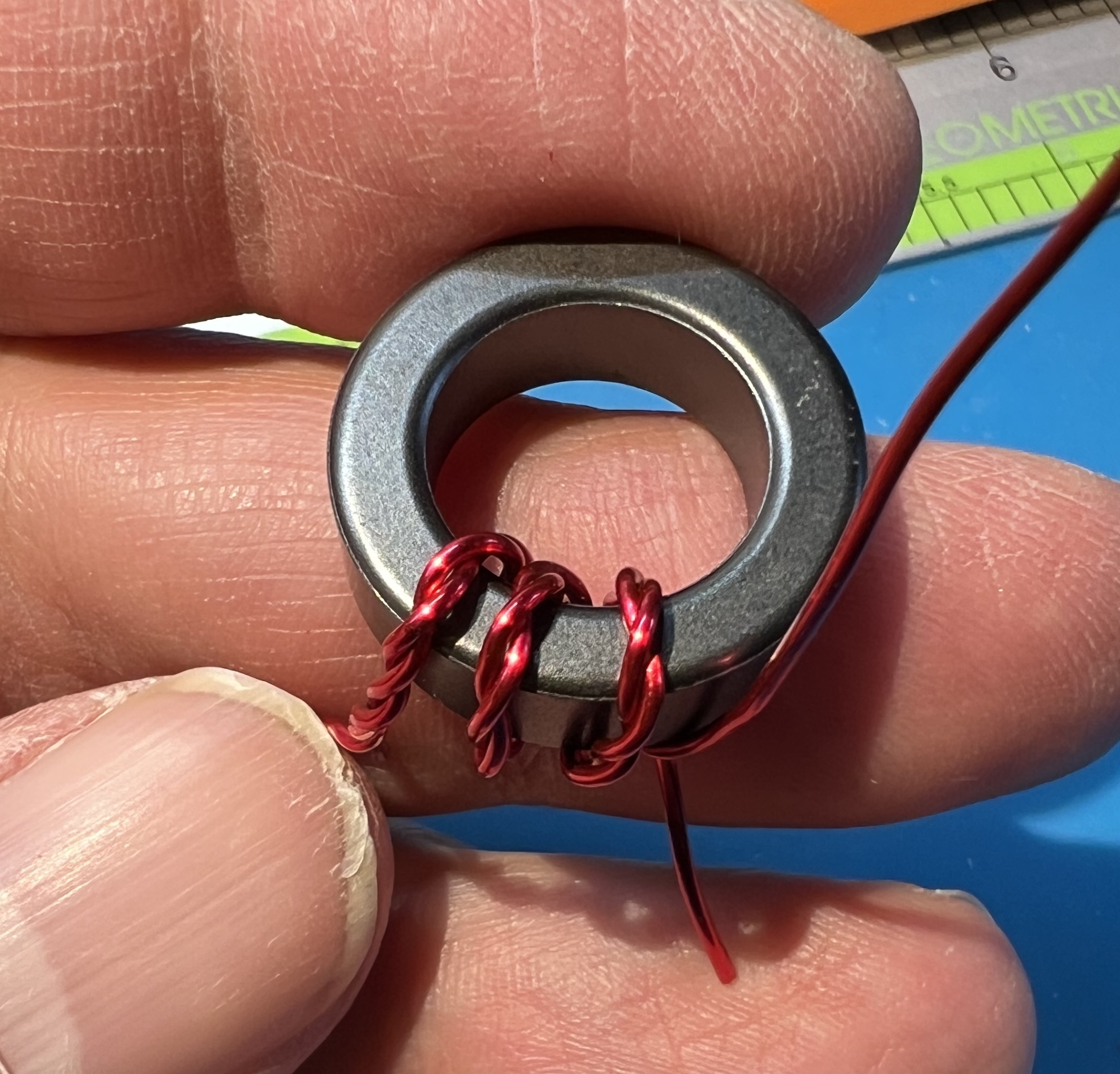
Cut your 8" wire from your length of wire. Fold them both in half to find the middle of each wire. Folded wire Folded wire

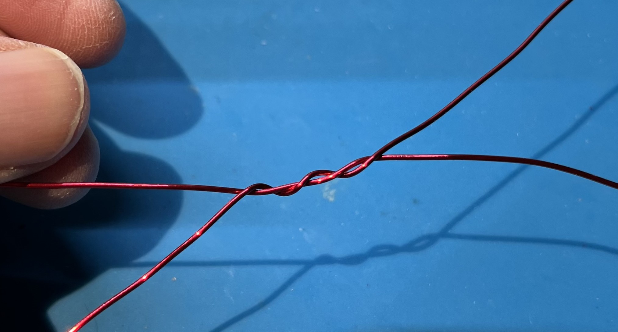
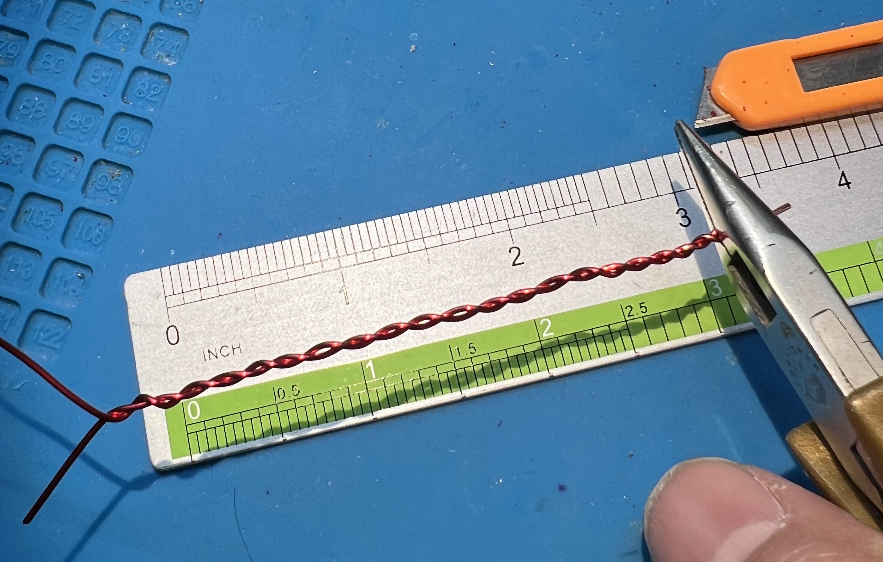
Grip the wire in the middle and twist some in each direction. Grip to twist Grip to twist Twisted wires Twisted wires

You need about 6" of twisted wire. Twisted wires and ruler Twisted wires and ruler

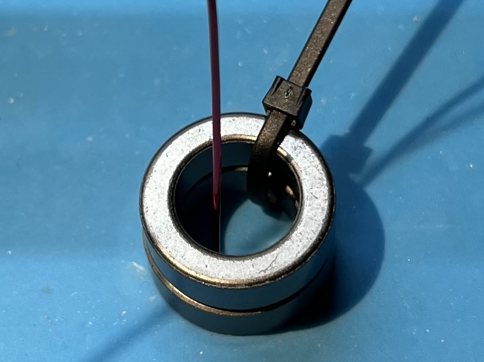
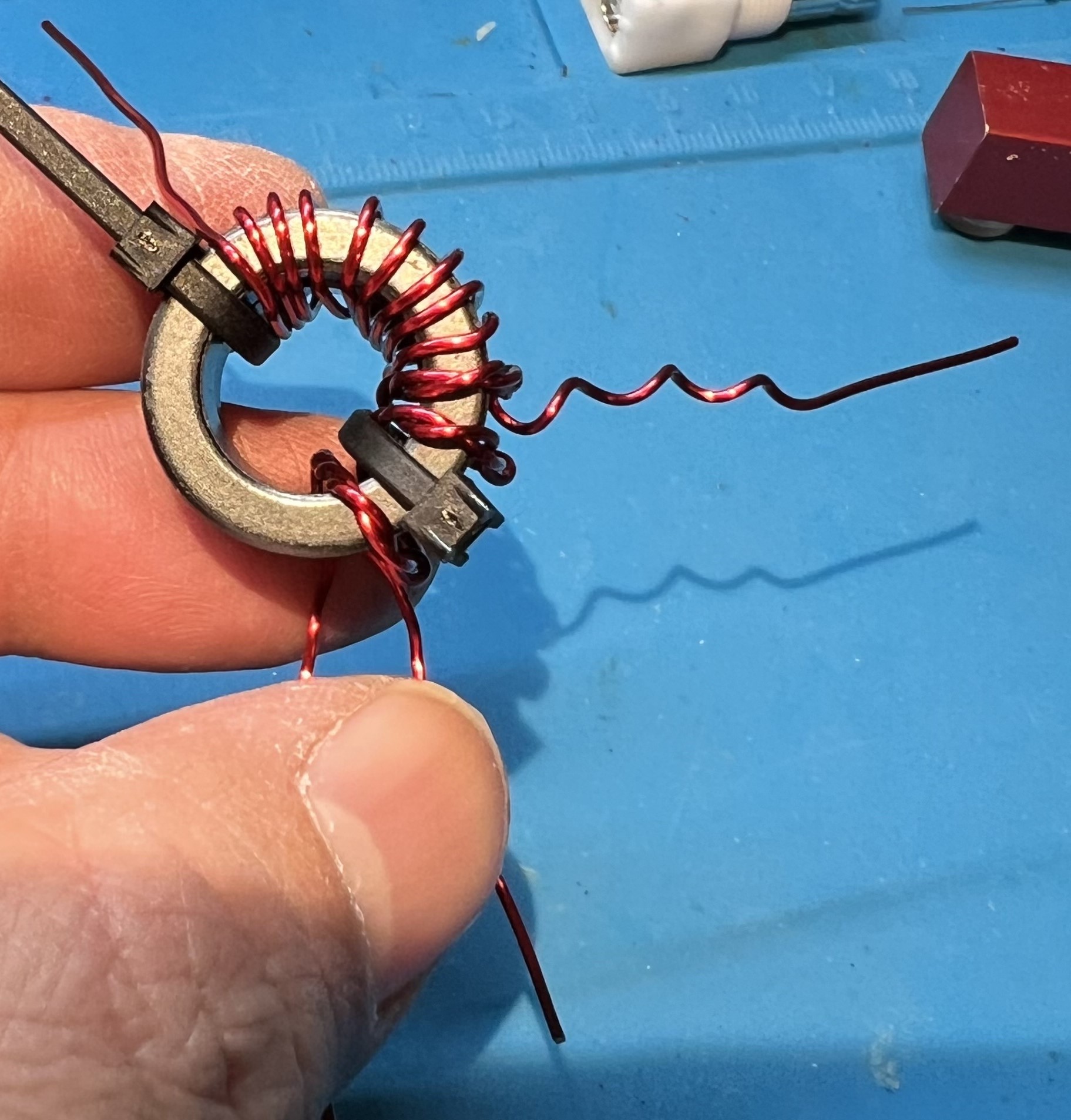
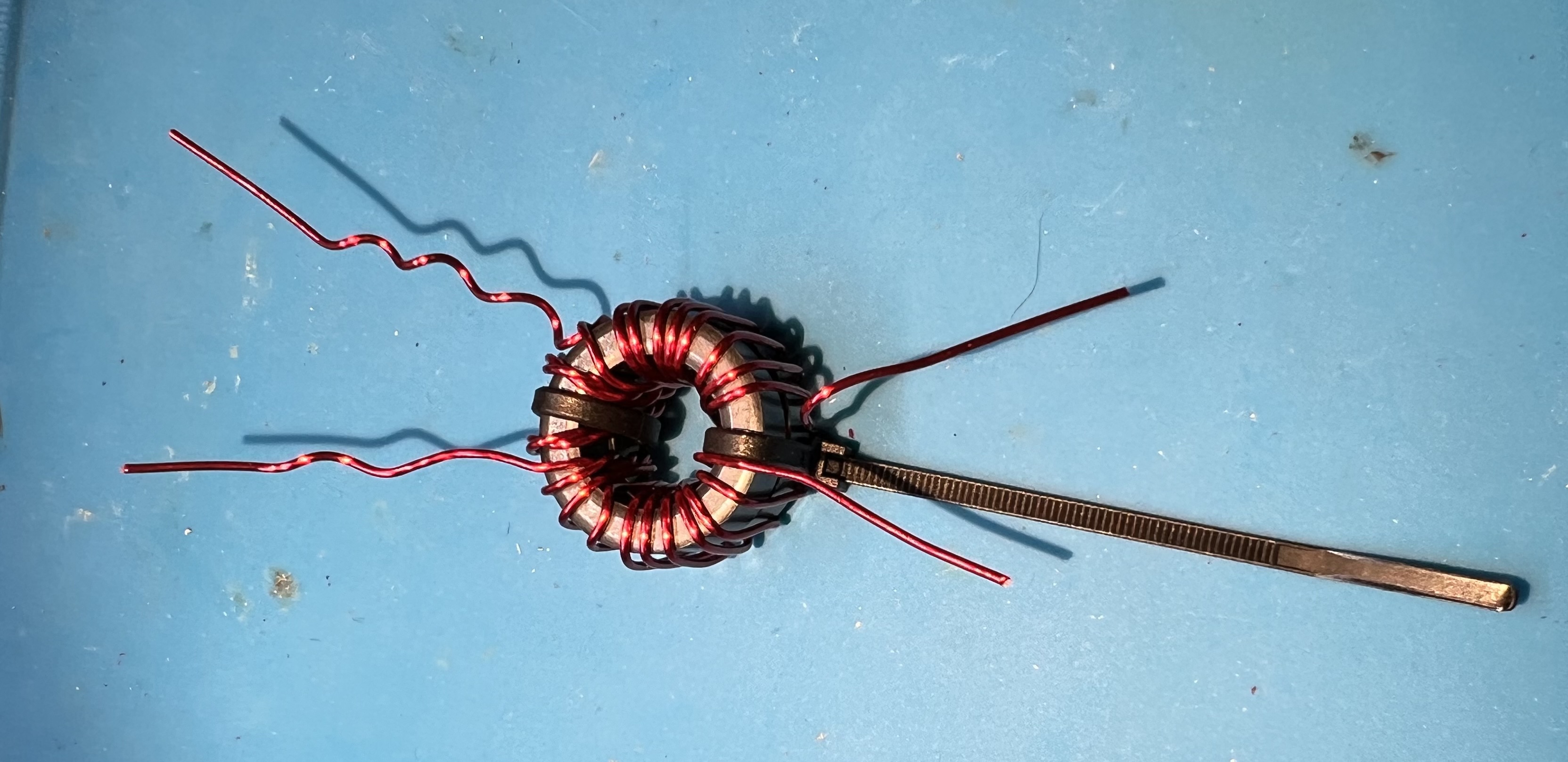
Use one of the zip ties to hold the double stacked toroids together. Insert an end of the wire through from the top. Double stack joined and wire Double stack joined and wire

Place the first turn of the twisted wire on the toroid. This should be in the middle of the twisted section. First turn First turn

Use the second zip tie to secure the first (middle) turn of the twisted wire on the toroid. Secure the first turn Secure the first turn

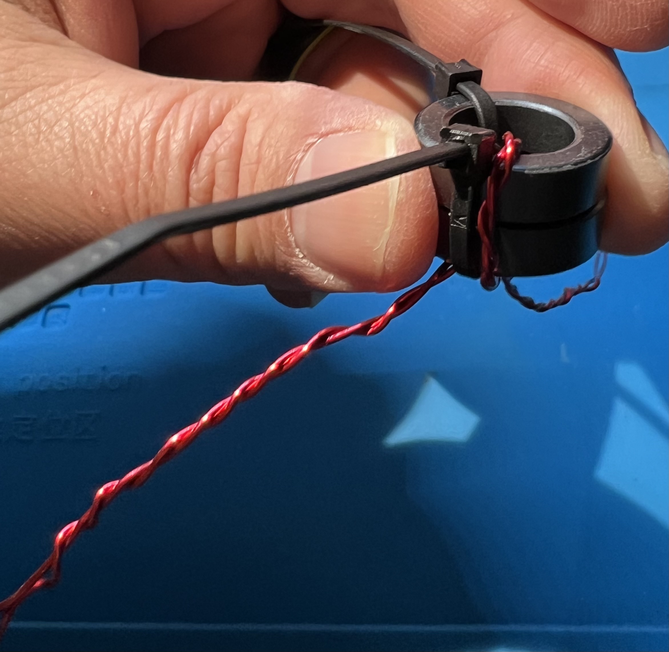
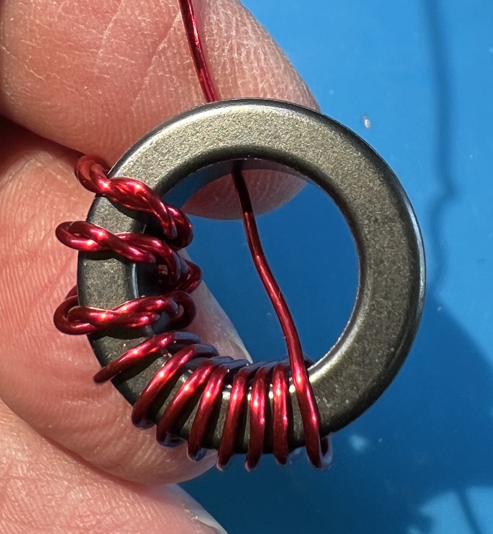
Wrap an additional turn with both wires to the left (clockwise). Additionl primary turn clockwise Additionl primary turn clockwise

Wrap an additional turn with both wires to the right (counter-clockwise). Additional primary turn counter-clockwise Additional primary turn counter-clockwise

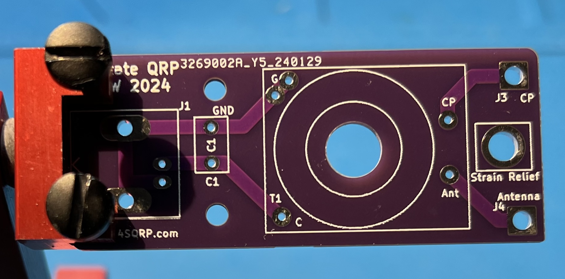
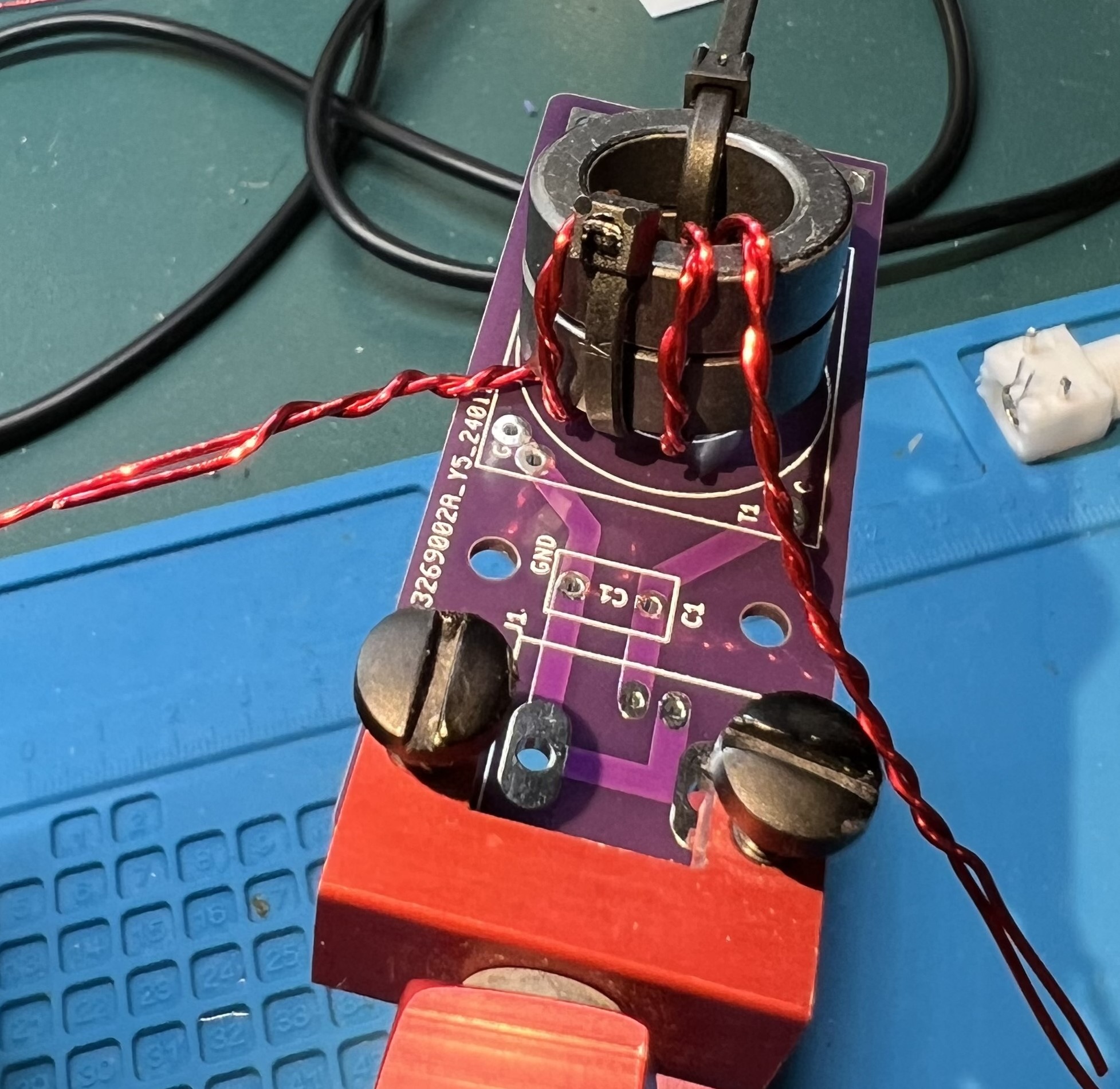
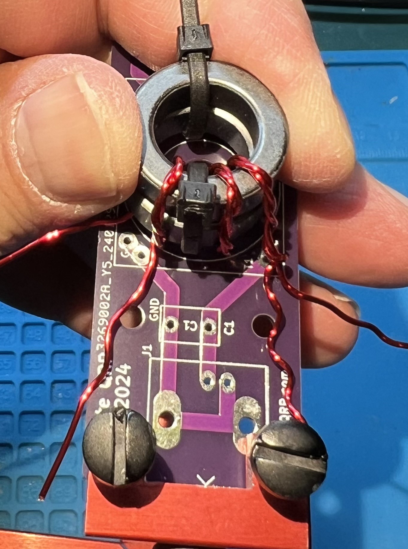
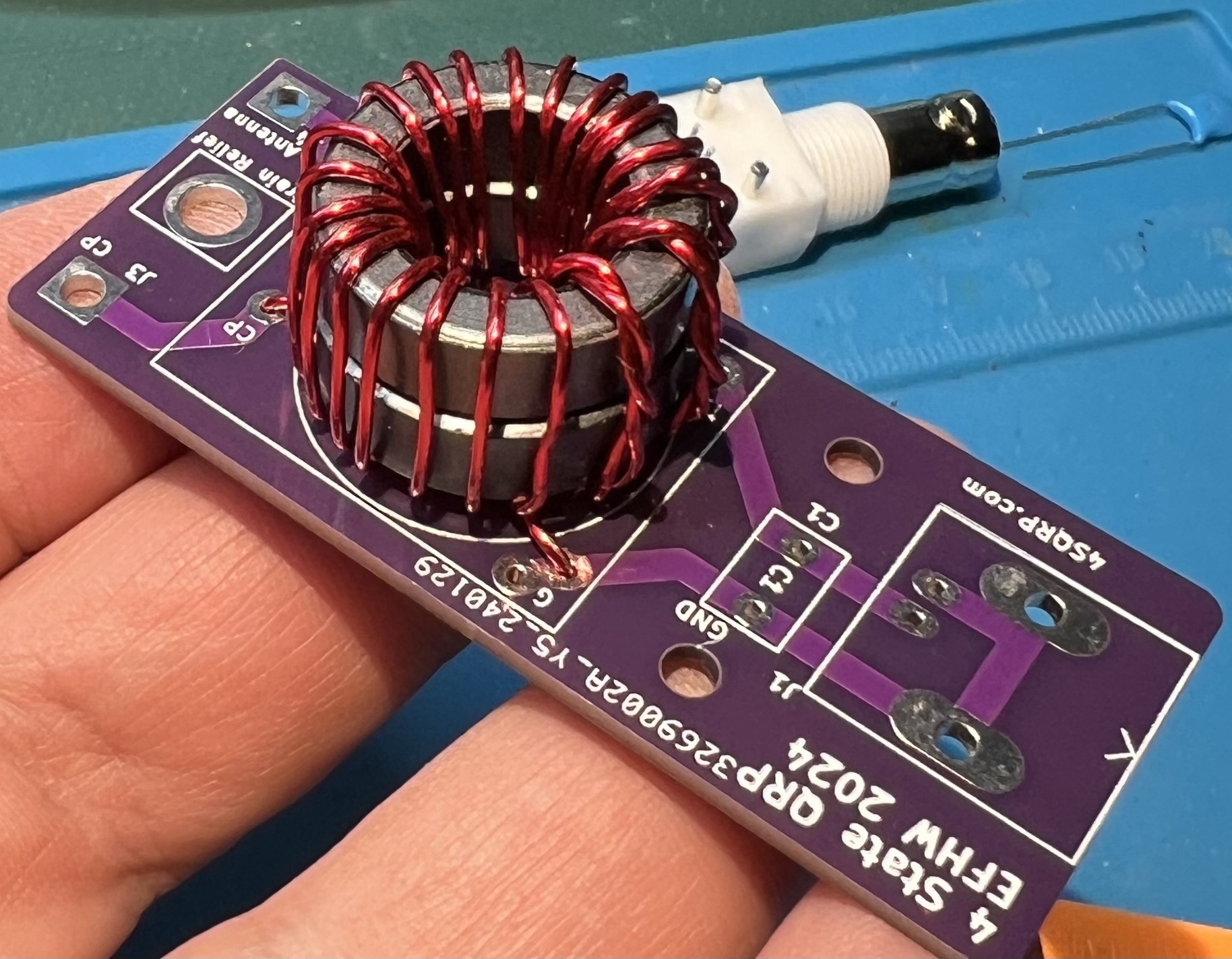
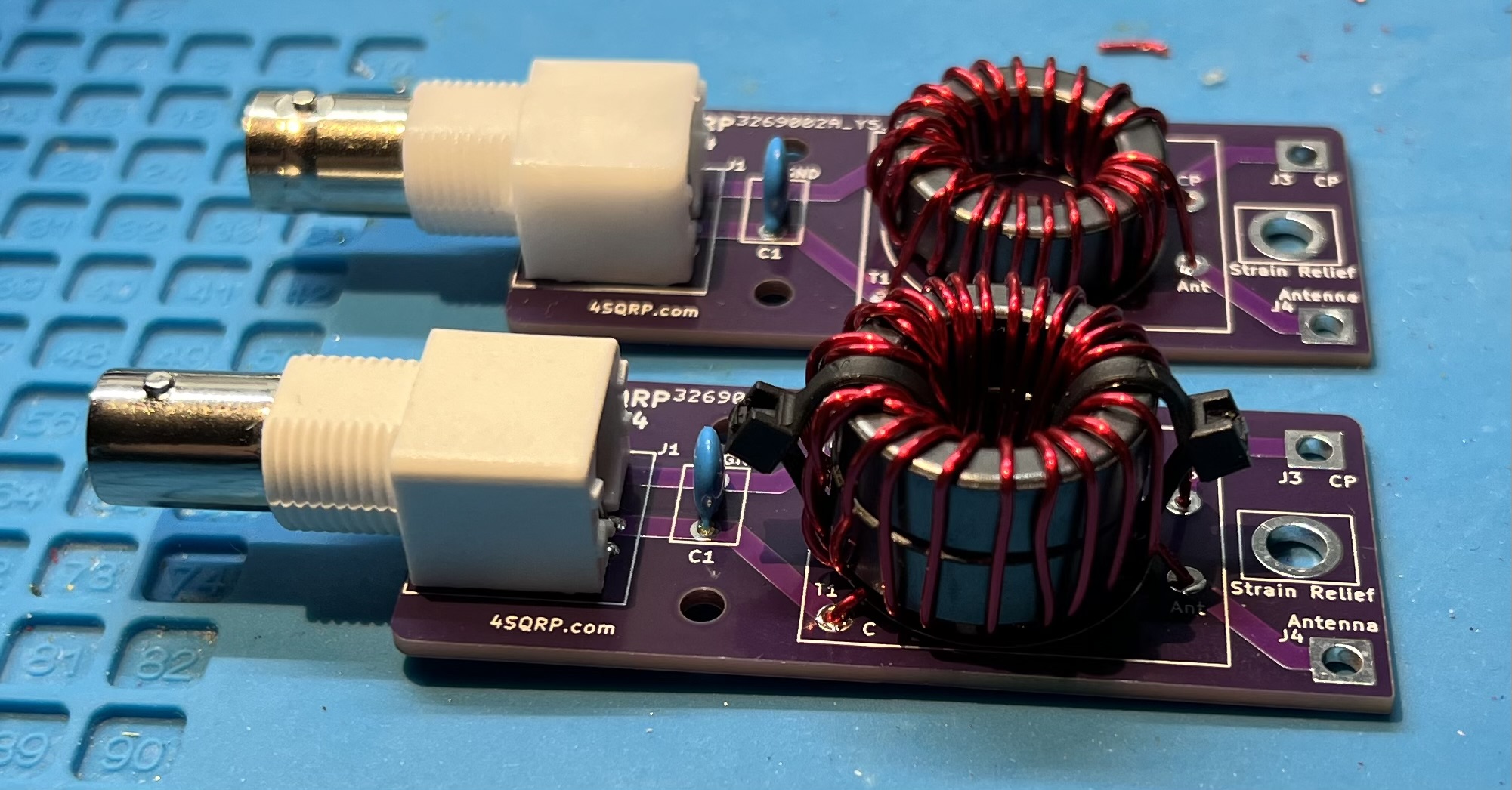
Check the twisted section against the location of the holes for the primary. The holes are labeled G and C, inside the T1 block, near the C1 component box. Untwist the wires as necessary so that you can cleanly reach the holes and with the other longer wire continue wrapping the secondary. Primary Length Primary Length

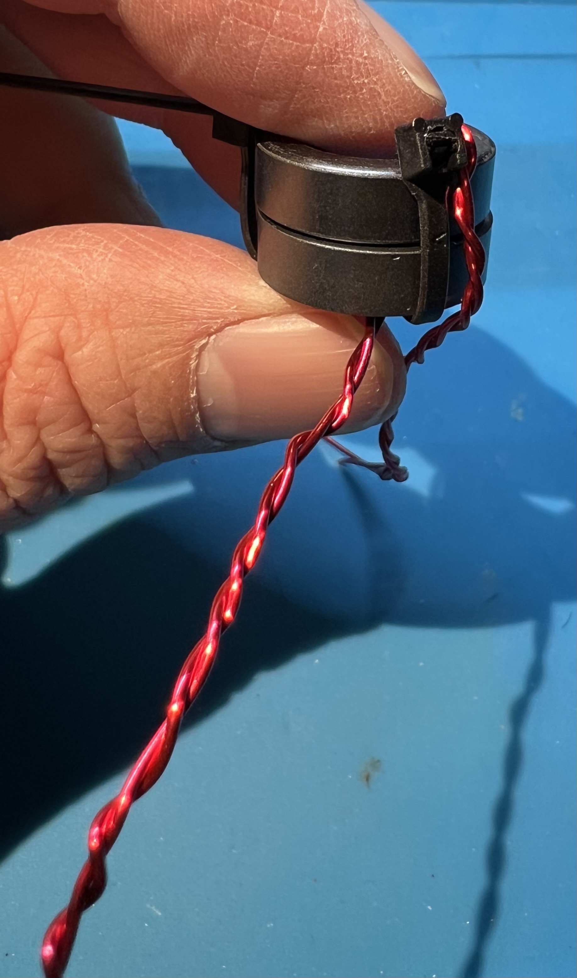
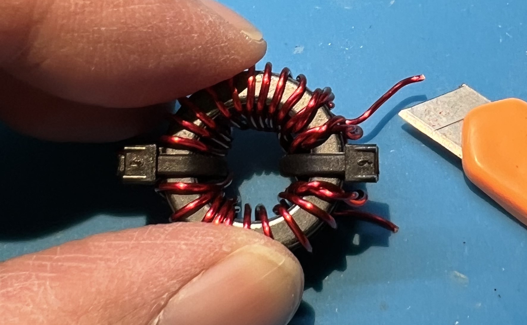
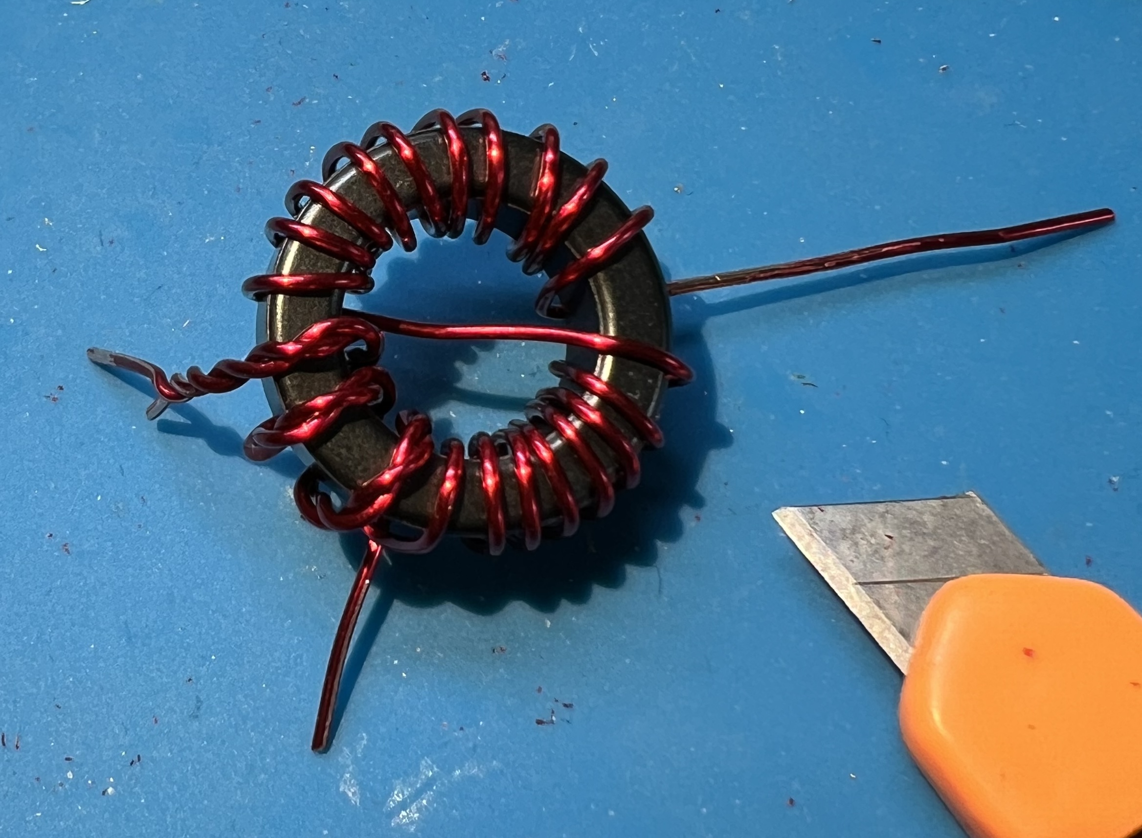
The untwisted primary that goes into the C hole and the continued counter-clockwise secondary winding. You should count from the center double wrapped wire of the primary, counterclockwise the wire passing through the center of the toroid 11 times. That will be the middle twisted wire and one more twisted wire to the right. Followed by 9 more turns of single secondary wire. Counter-clockwise windings Counter-clockwise windings

Now, do the same thing but continuing clockwise. Start from the middle winding of the twisted wires. Count it and one more twisted to the left. Now wind 9 more to the left. Clockwise windings Clockwise windings

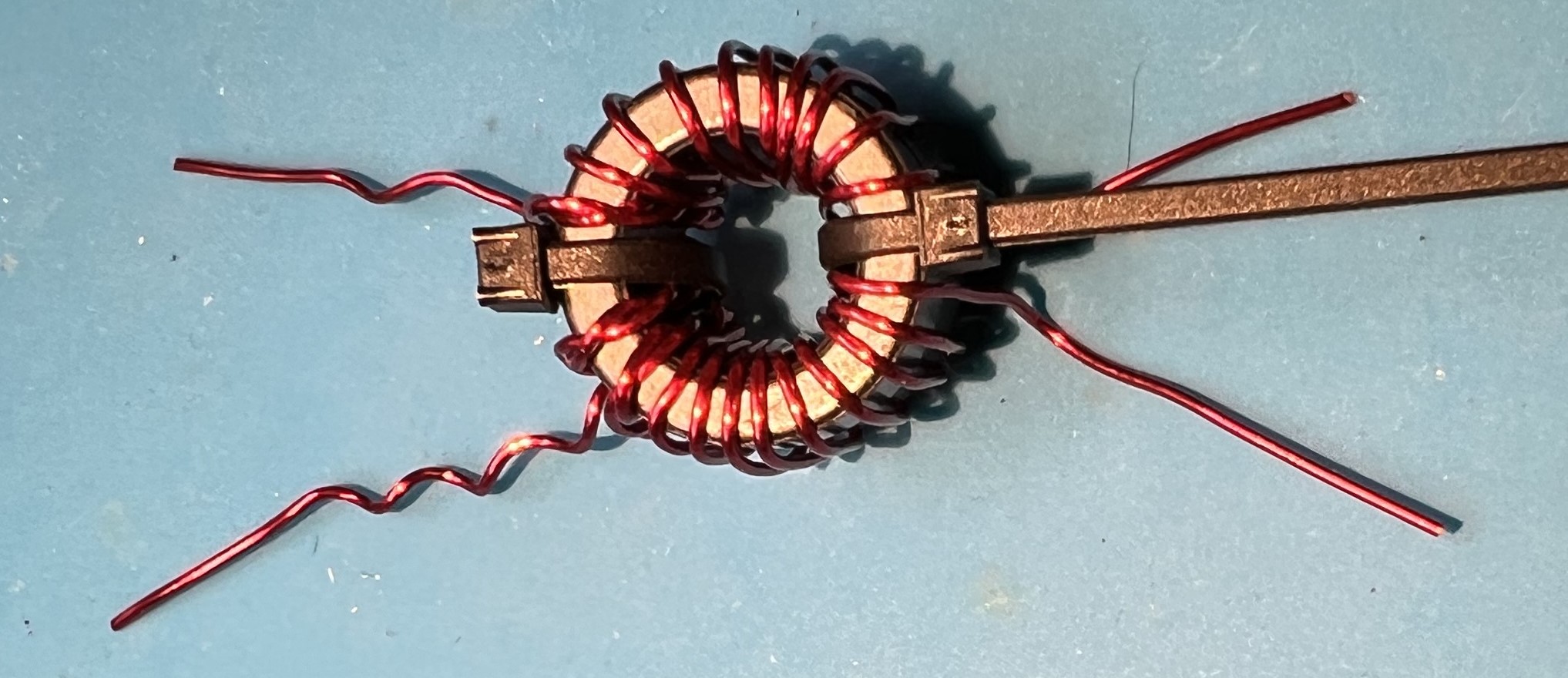
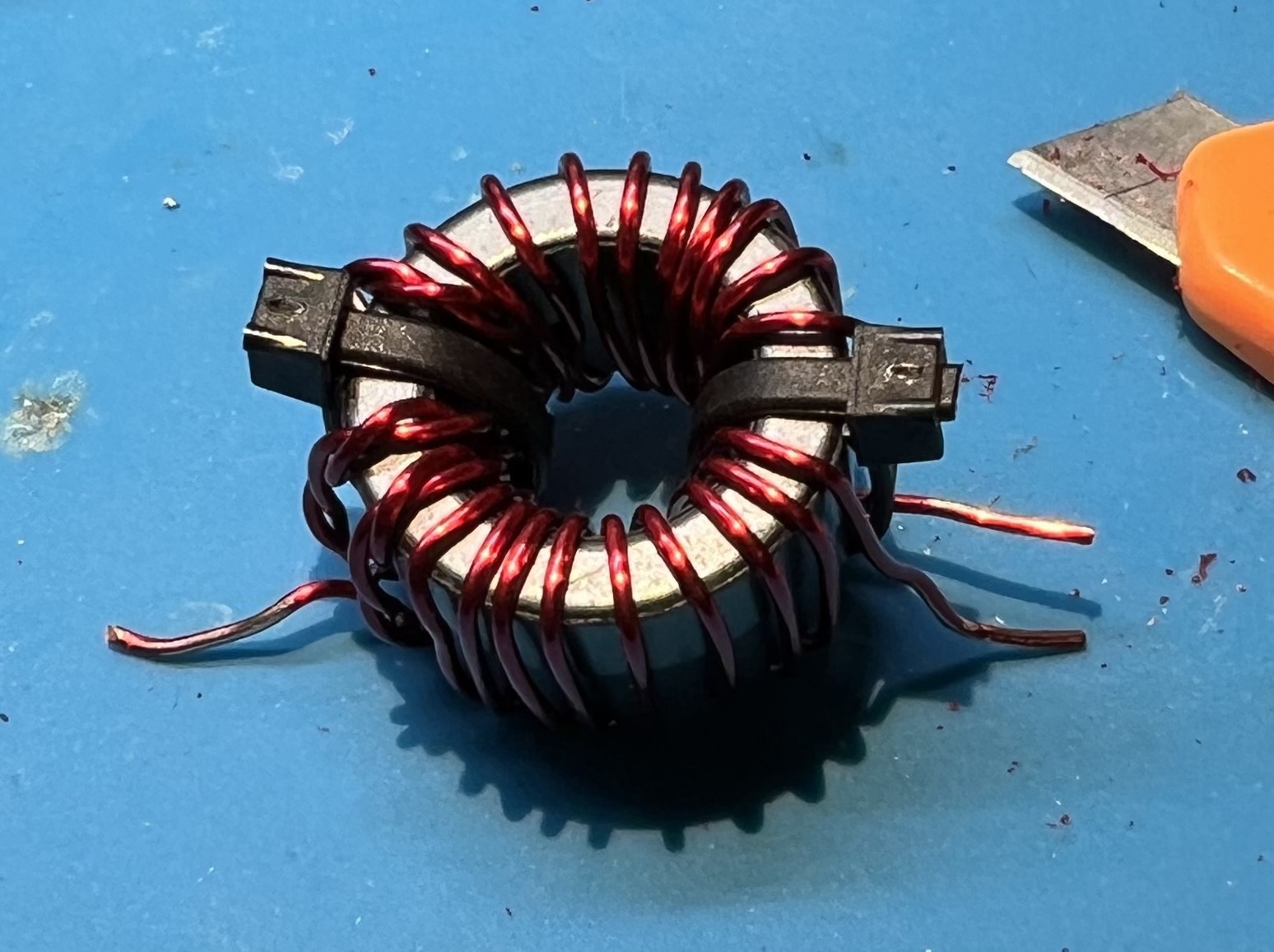
In total you will have 21 windings. But, we counted 11 twice you protest! Well, that’s because we counted the first winding (the middle winding) each time. Wound toroid Wound toroid

Now is a good time to give yourself a pat on the back or take a break.

Placing and soldering

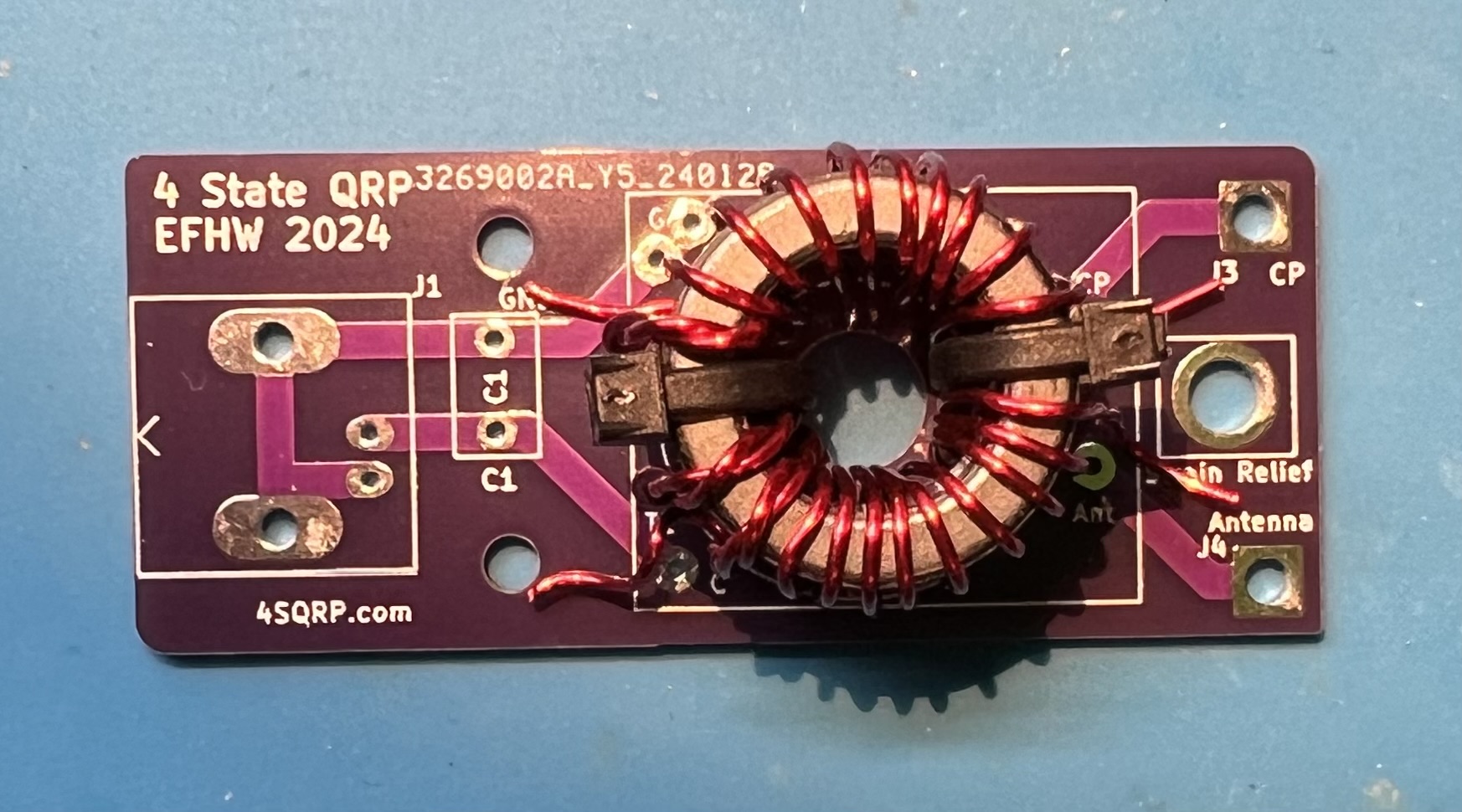
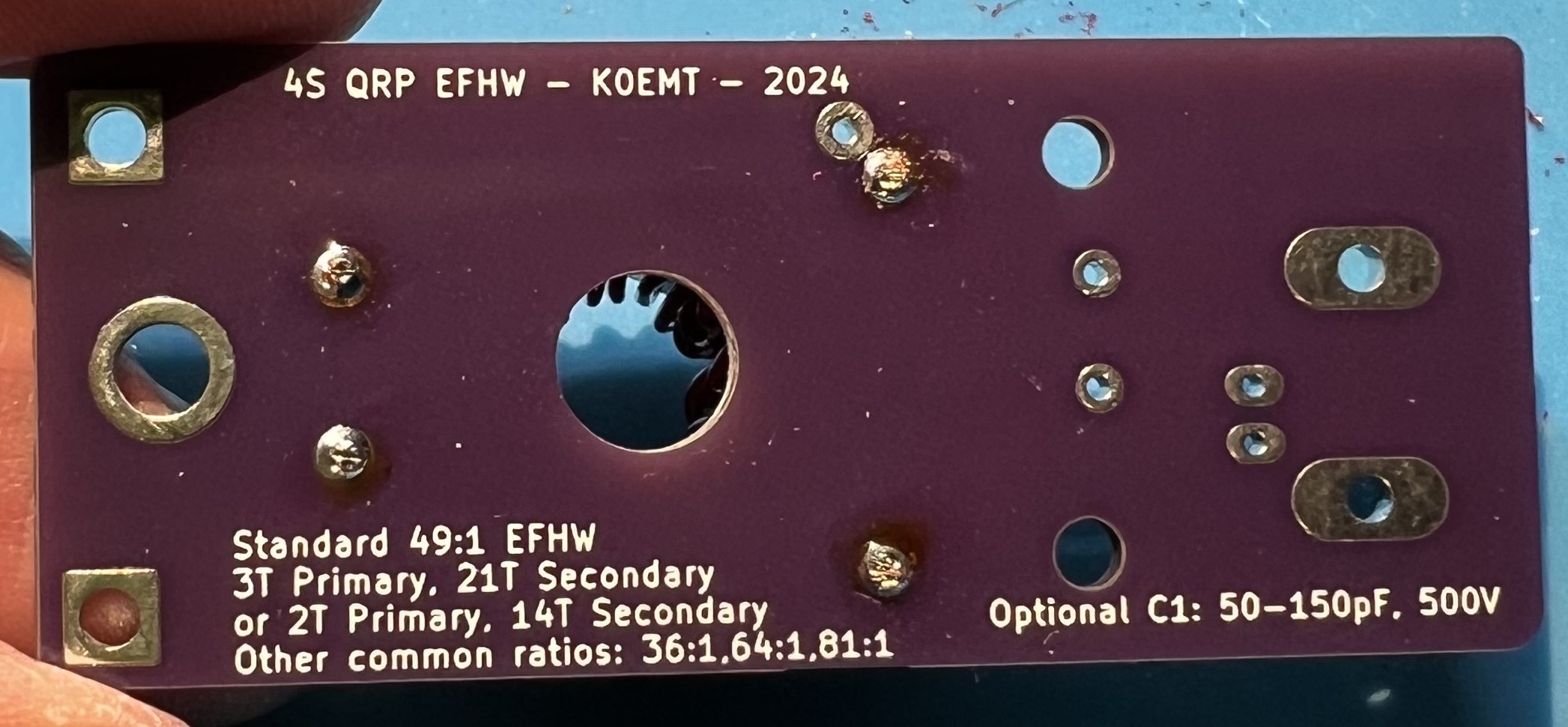
Place the prepped transformer against the board. Line up the wires against the through holes. Verify you can get the wires in the holes. Trim the wires, but leave some excess. Lining up Lining up

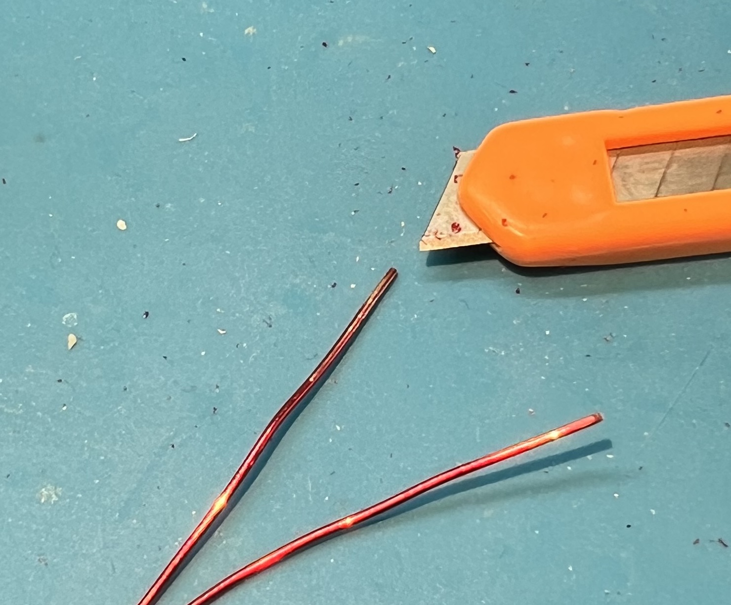
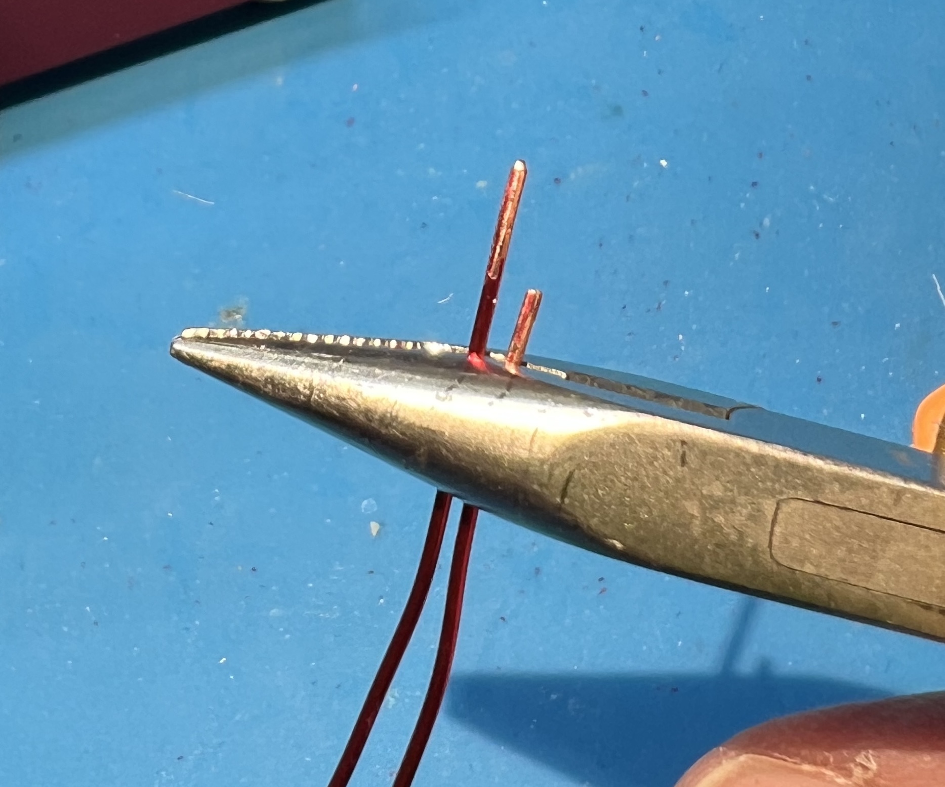
Use a utility knife to remove enamel coating from the wire where you will be soldering. I like to use a technique of holding the blade at a 45 degree angle against the wire. Then either work the blade against the wire, or hold the blade and pull the wire. You will need to be very careful to not nick or damage the wire itself. Remember to rotate the transformer so that you can scrape all around the wire where it will be soldered. Remove enamel 1 Remove enamel 1 Remove enamel 2 Remove enamel 2

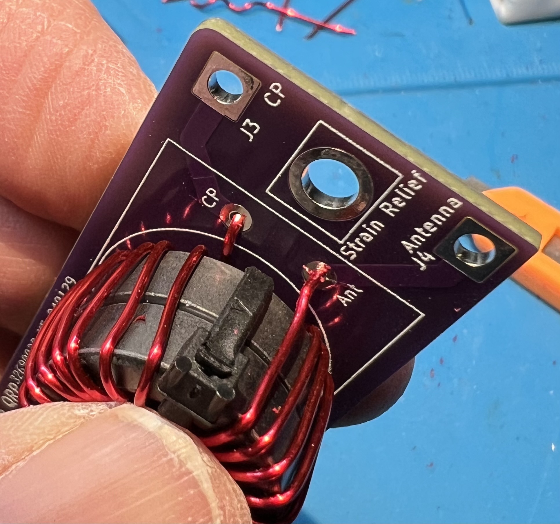
Get the primary side of the transformer into position. Placing the primary Placing the primary Placing the primary below Placing the primary below

Get lengths and routing checked for the secondary side of the transformer. Secondary top Secondary top Secondary leads Secondary leads

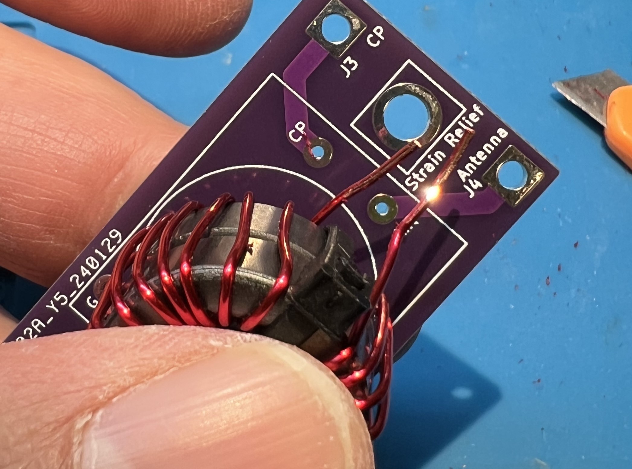
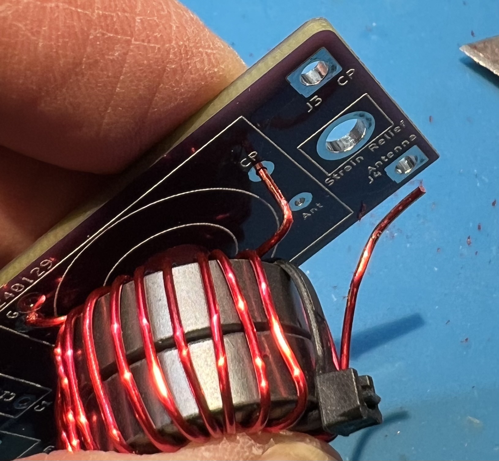
Note the bend you’ll need to get the CP end of the secondary transformer in to place. Mini pliers can help with this. Placement for secondary in CP Placement for secondary in CP Secondary wires in place CP and Ant Secondary wires in place CP and Ant

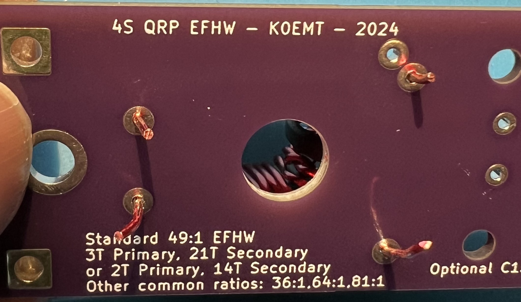
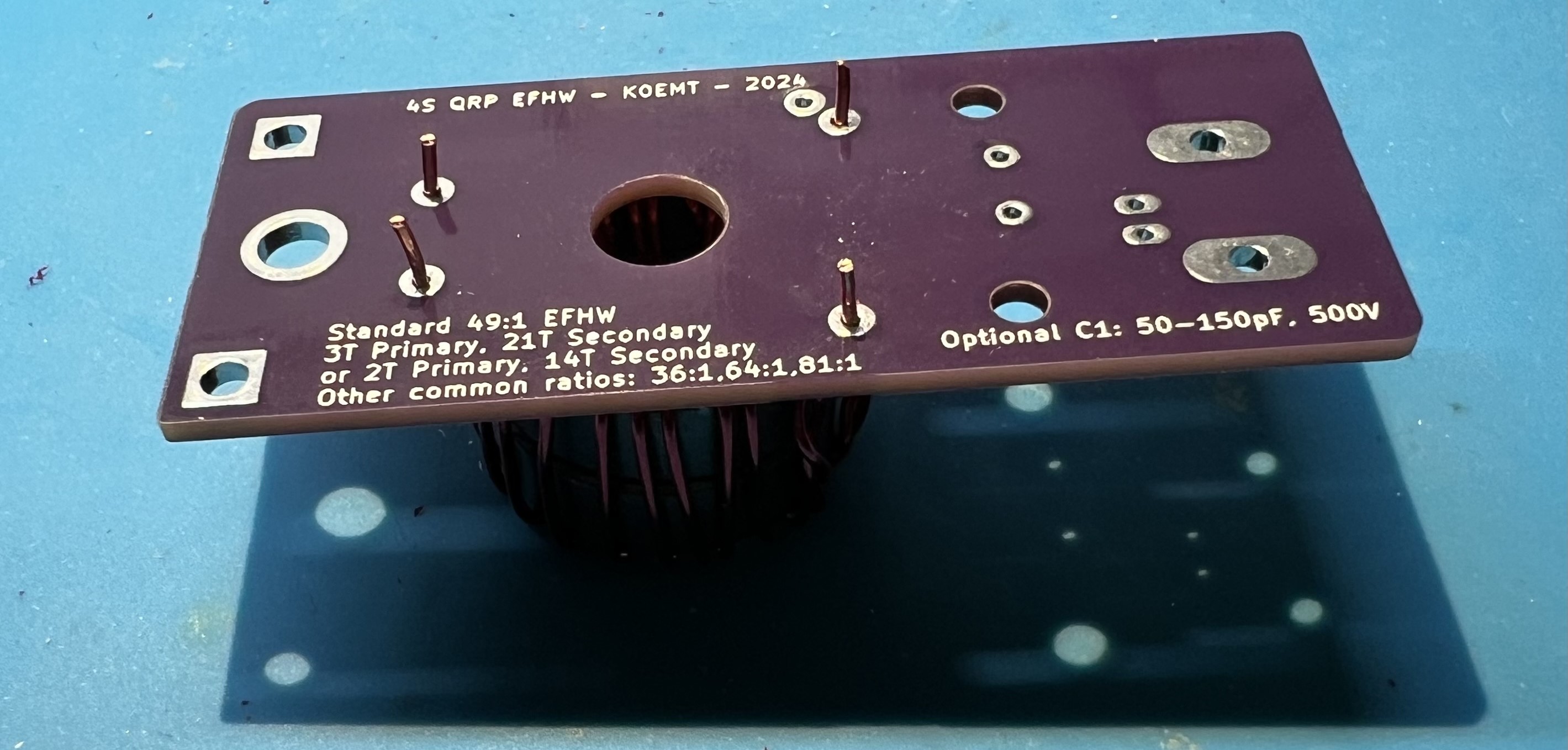
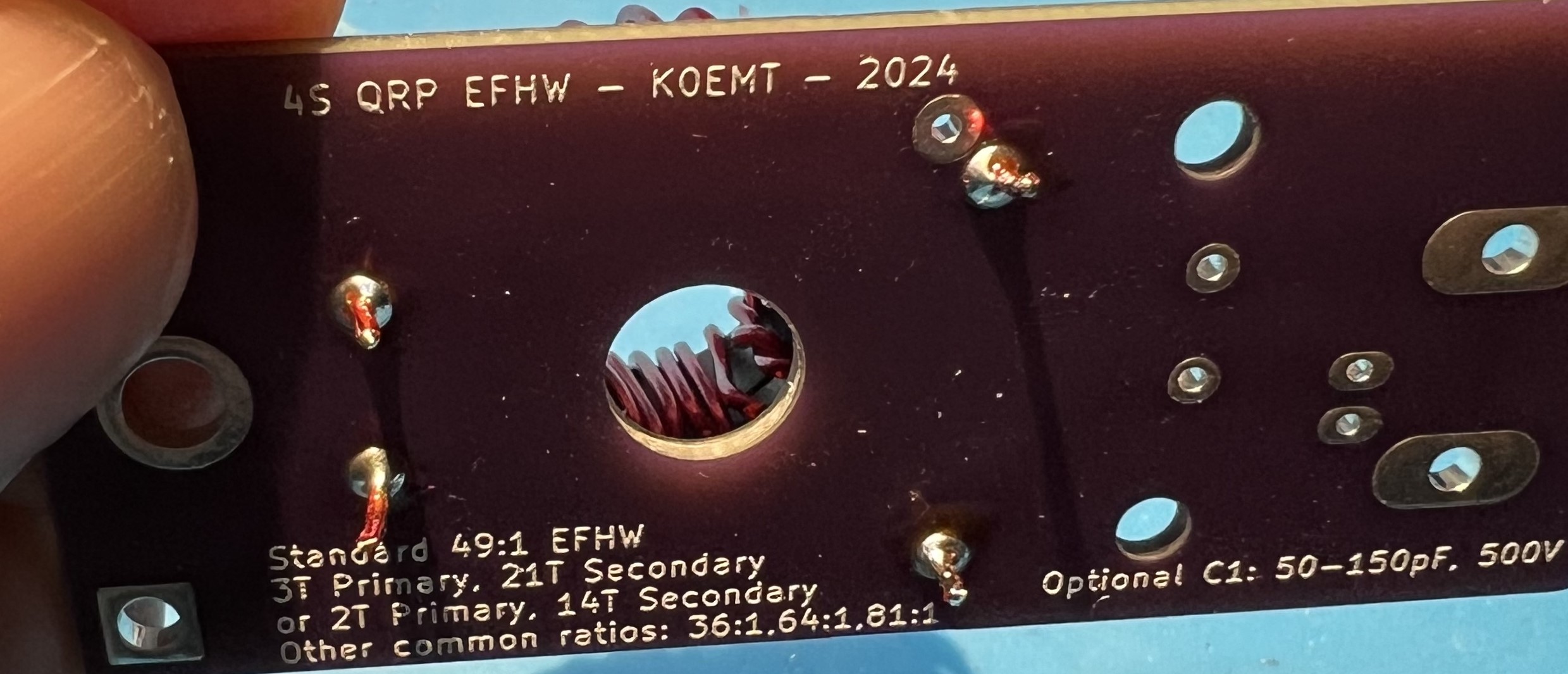
View the transformer leads from the underside of the board. Transformer leads from below Transformer leads from below

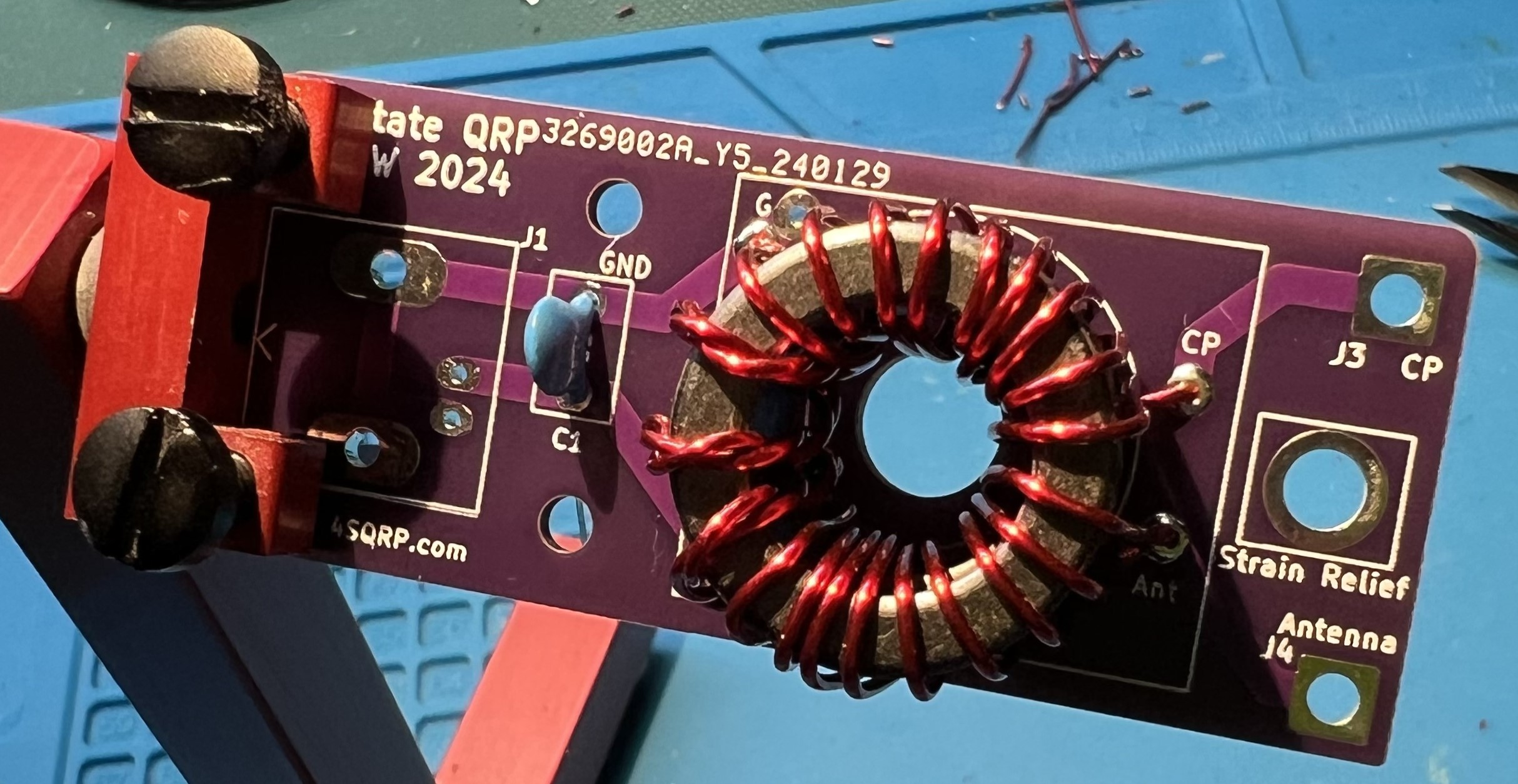
The transformer placement viewed from above and primary side. NOTE: at this time the zip ties have been removed. Transformer placement primary view Transformer placement primary view

Wire leads trimmed a bit more, ready to solder. Avoid overheating the wire and melting enamel further up into the toroid. Note that the blue surface pictured here is a heat resistant silicone mat. Wires trimmed, ready to solder Wires trimmed, ready to solder

Note that the solder is covering the pad and the wire where the enamel coating was removed. Soldered leads Soldered leads

Testing

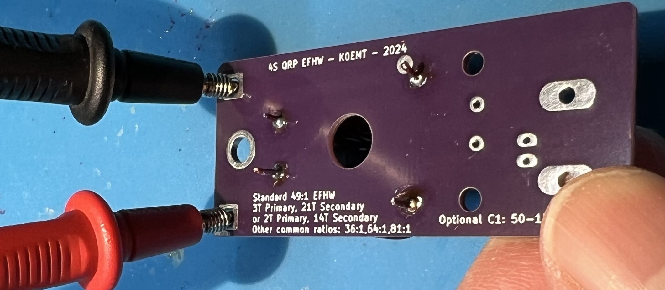
Test for good continuity on the secondary winding. Use an ohm meter to check for continuity between J3 CP and J4 Antenna on the output side.

If you don’t have continuity, that means you didn’t get the enamel off of the wire at the through holes of the secondary. Inspect and correct wires at CP and Antenna in the transformer block. Testing the secondary Testing the secondary

Check for continuity between the BNC mount holes and the secondary side CP and Antenna connections. You should not have continuity here. If you do have continuity, that means you have somehow shorted the primary and secondary wires. You will most likely need to remove the windings and restart with new wire. Testing for short Testing for short

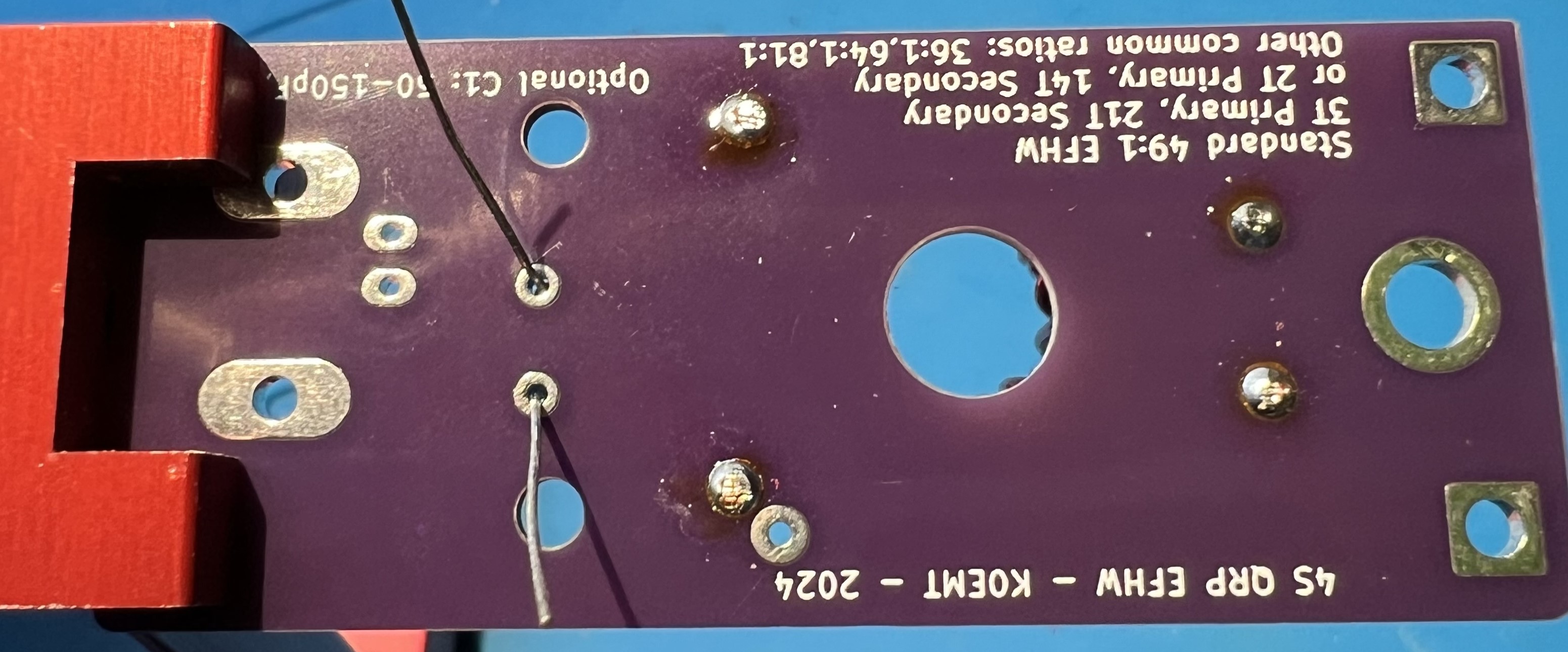
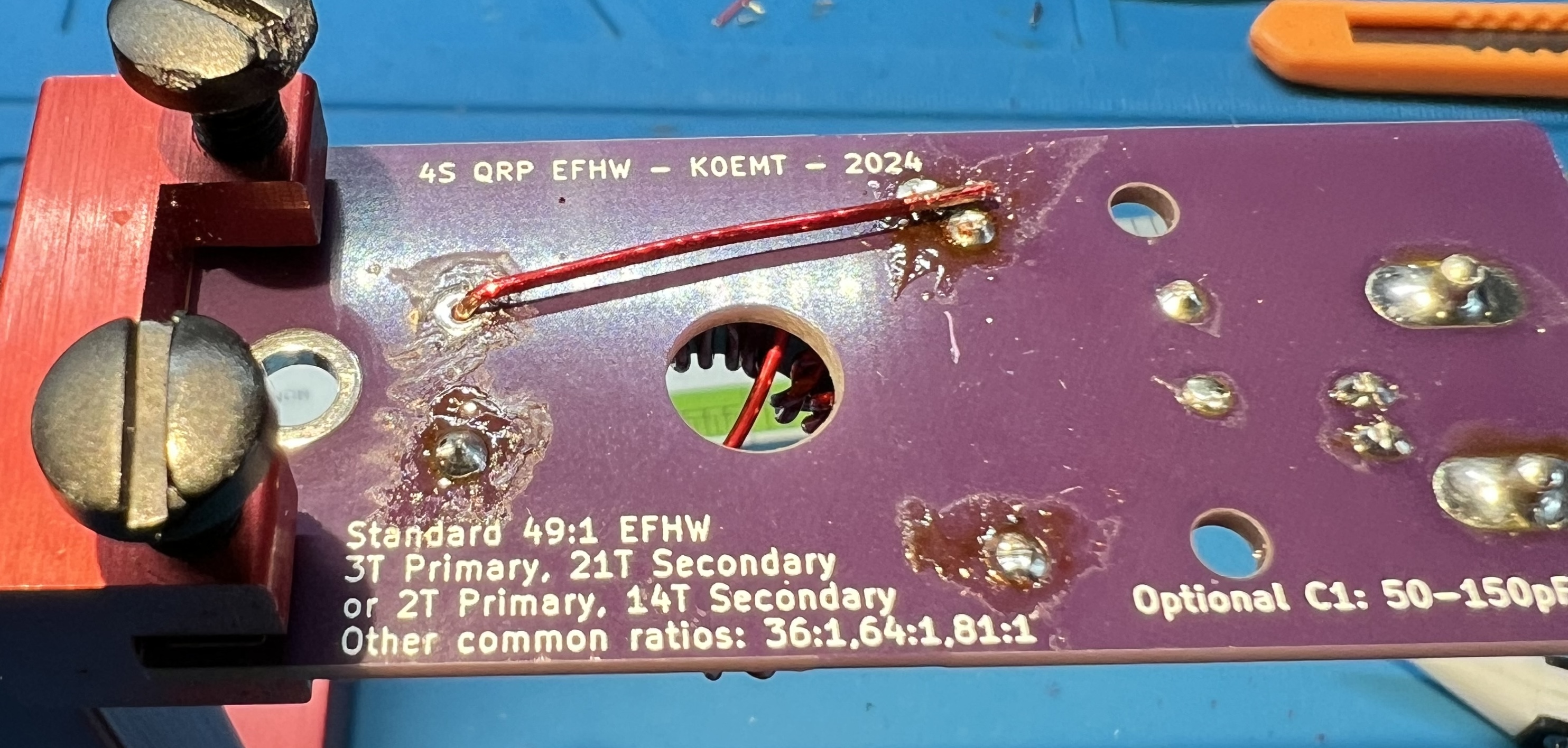
Flip the board over and test for continuity in the capacitor block C1. You should have continuity when you place your leads here. If you don’t have continuity, that means you didn’t get the enamel off of the wire at the through holes of the primary. Inspect and correct wires at G and C in the transformer block.

Wrapping up

Trim leads. Trim leads Trim leads

Solder the capacitor in place now. Placing capacitor Placing capacitor Capacitor on the bottom of the board Capacitor on the bottom of the board

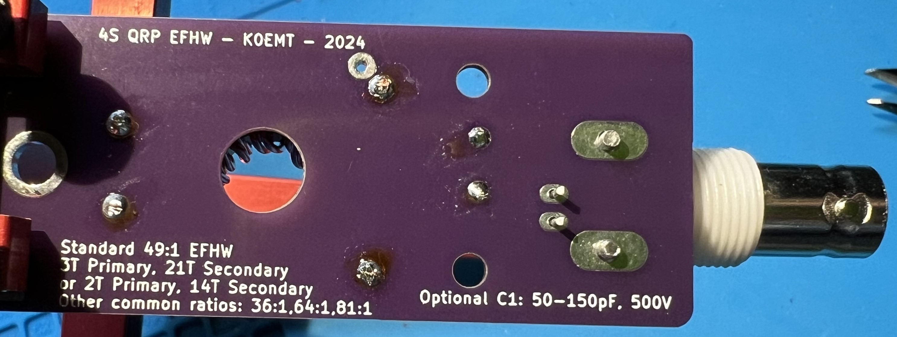
Solder the BNC in place now. Place the BNC Place the BNC Solder the BNC Solder the BNC

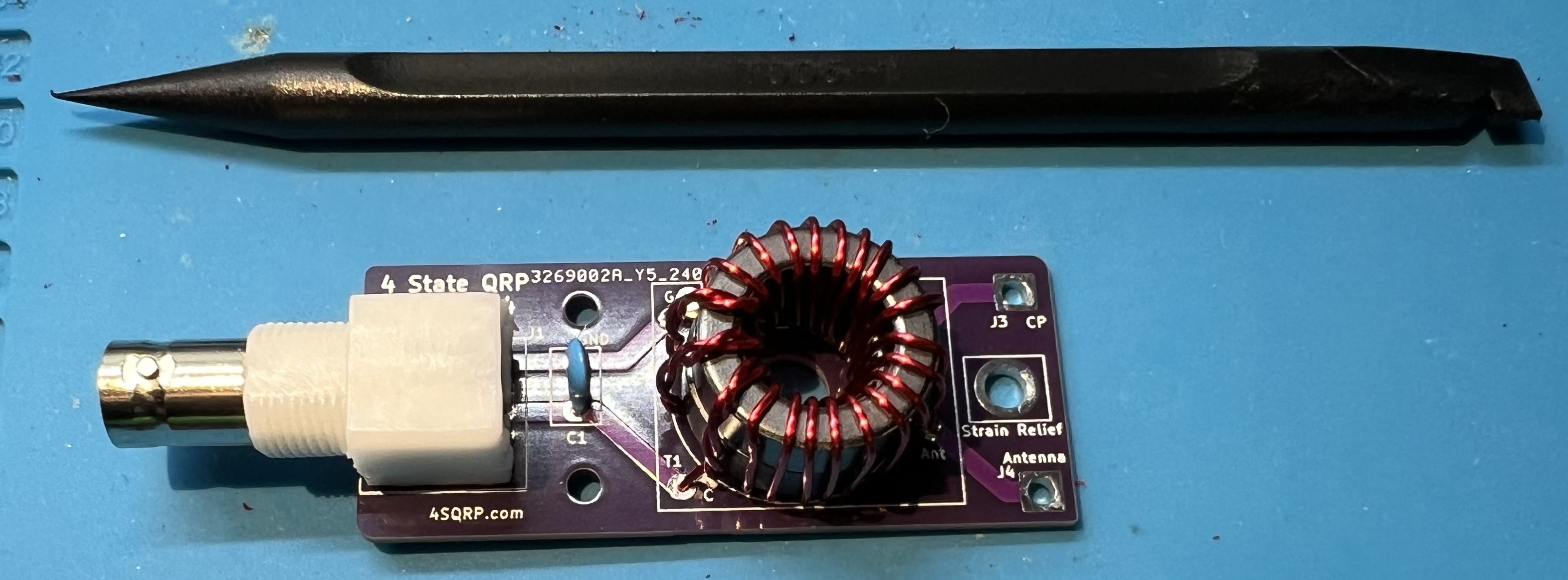
Use a spudger to spread the transformer turns both inside and around the core. The spudger is plastic and is used to avoid damaging the wire or the enamel coating. Transformer with spudger Transformer with spudger

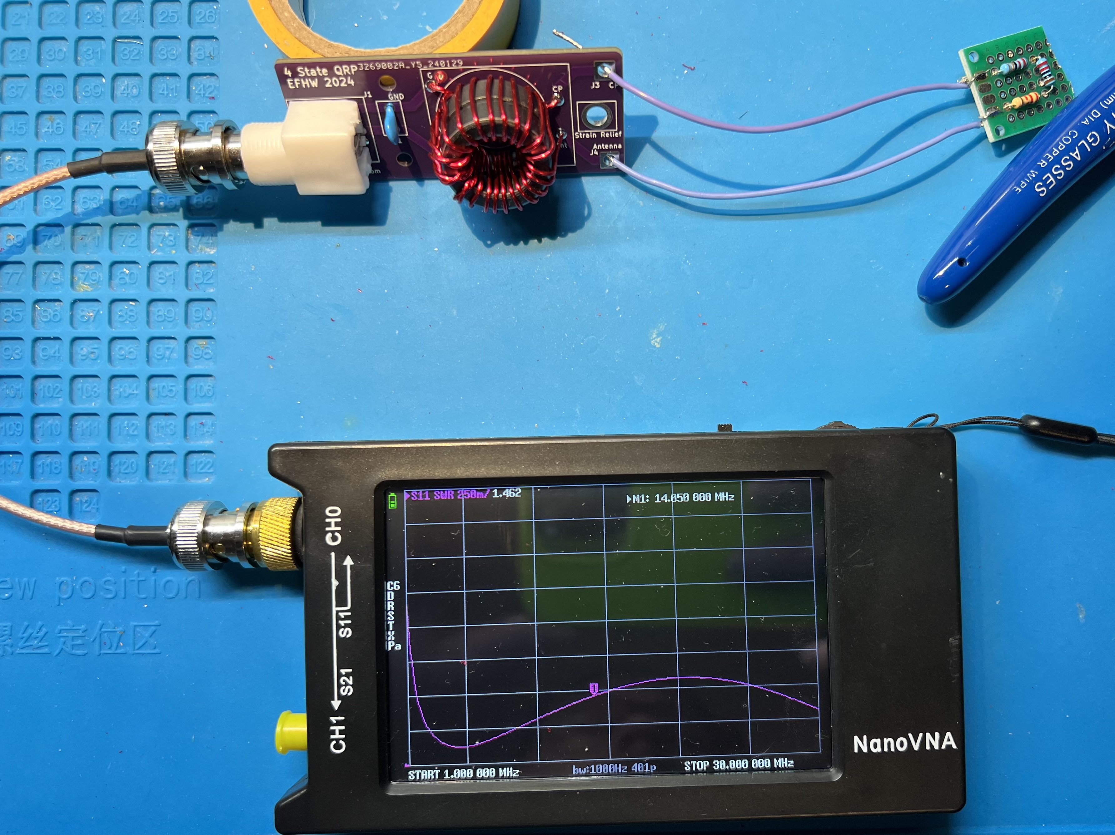
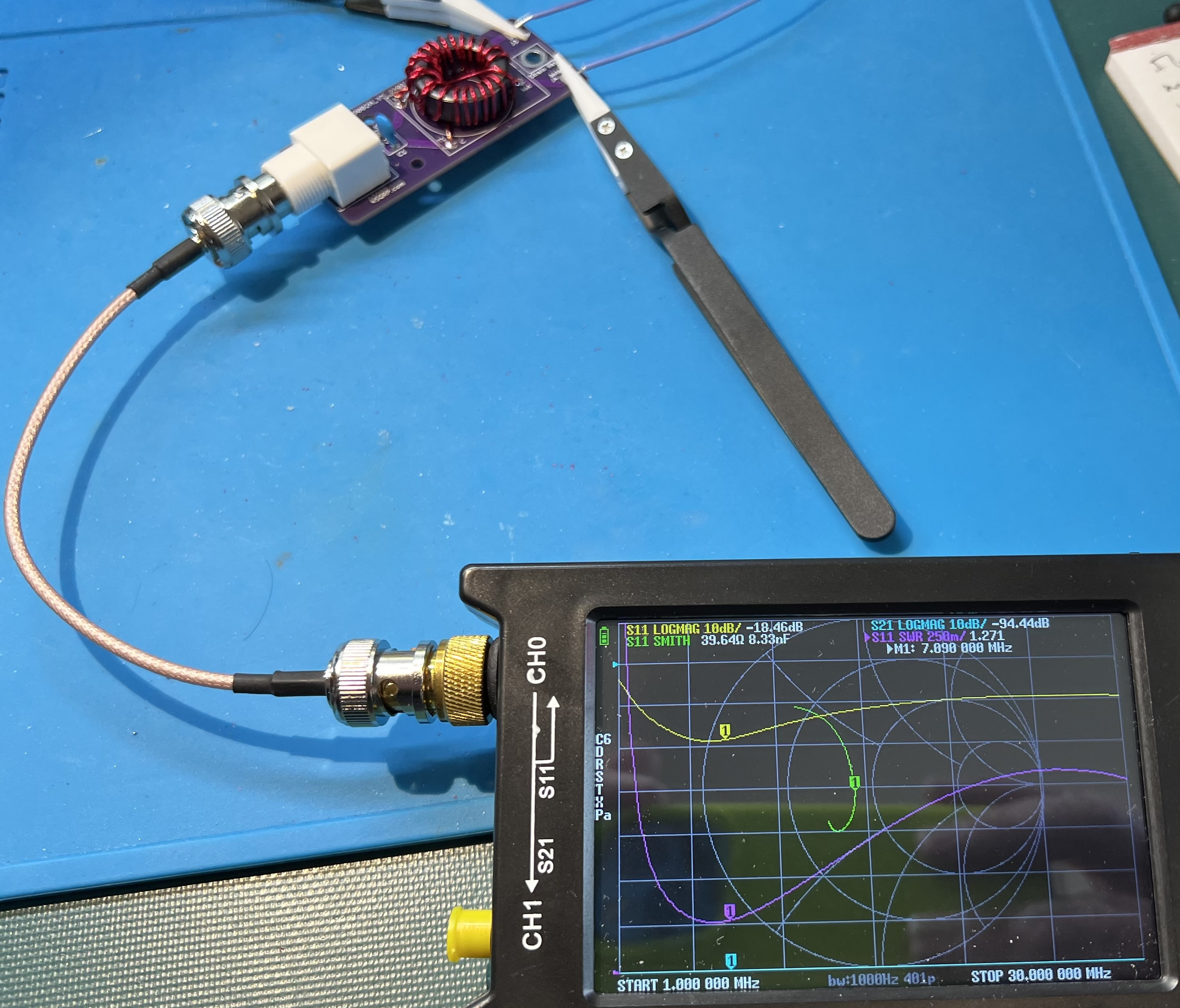
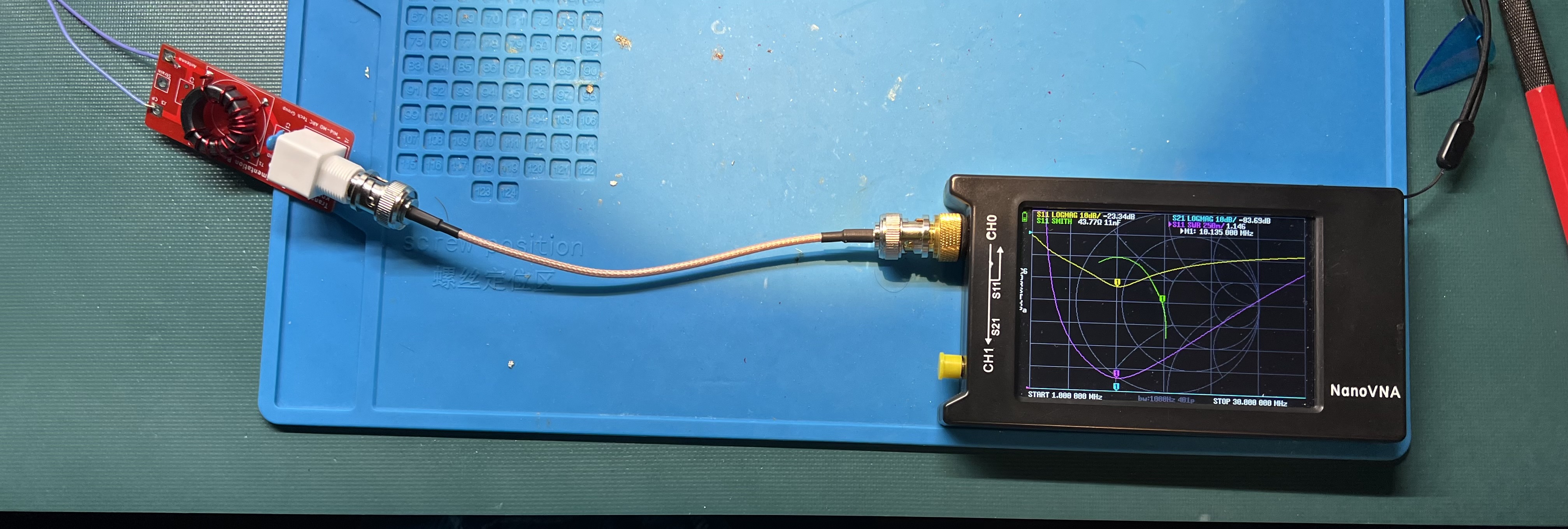
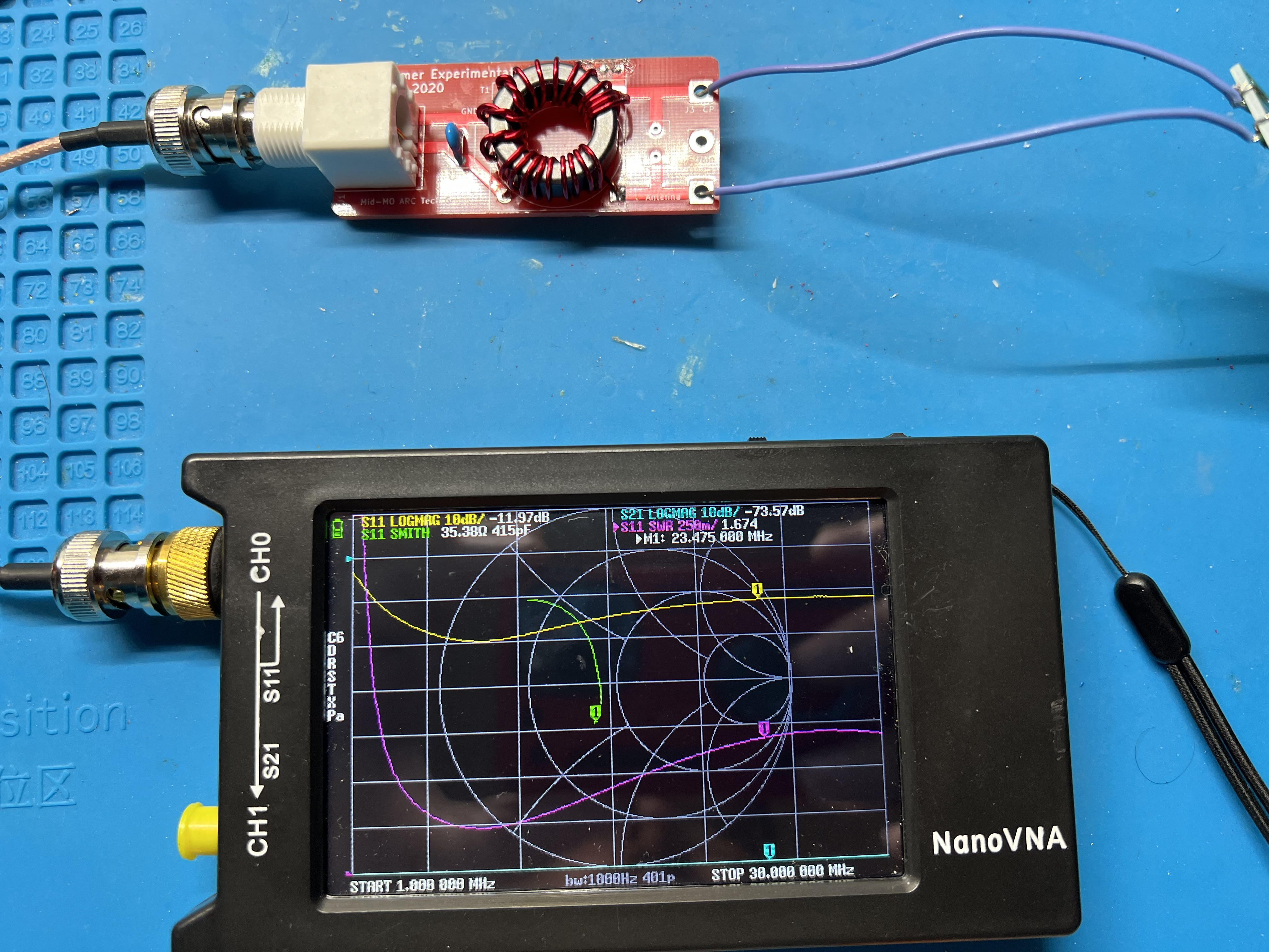
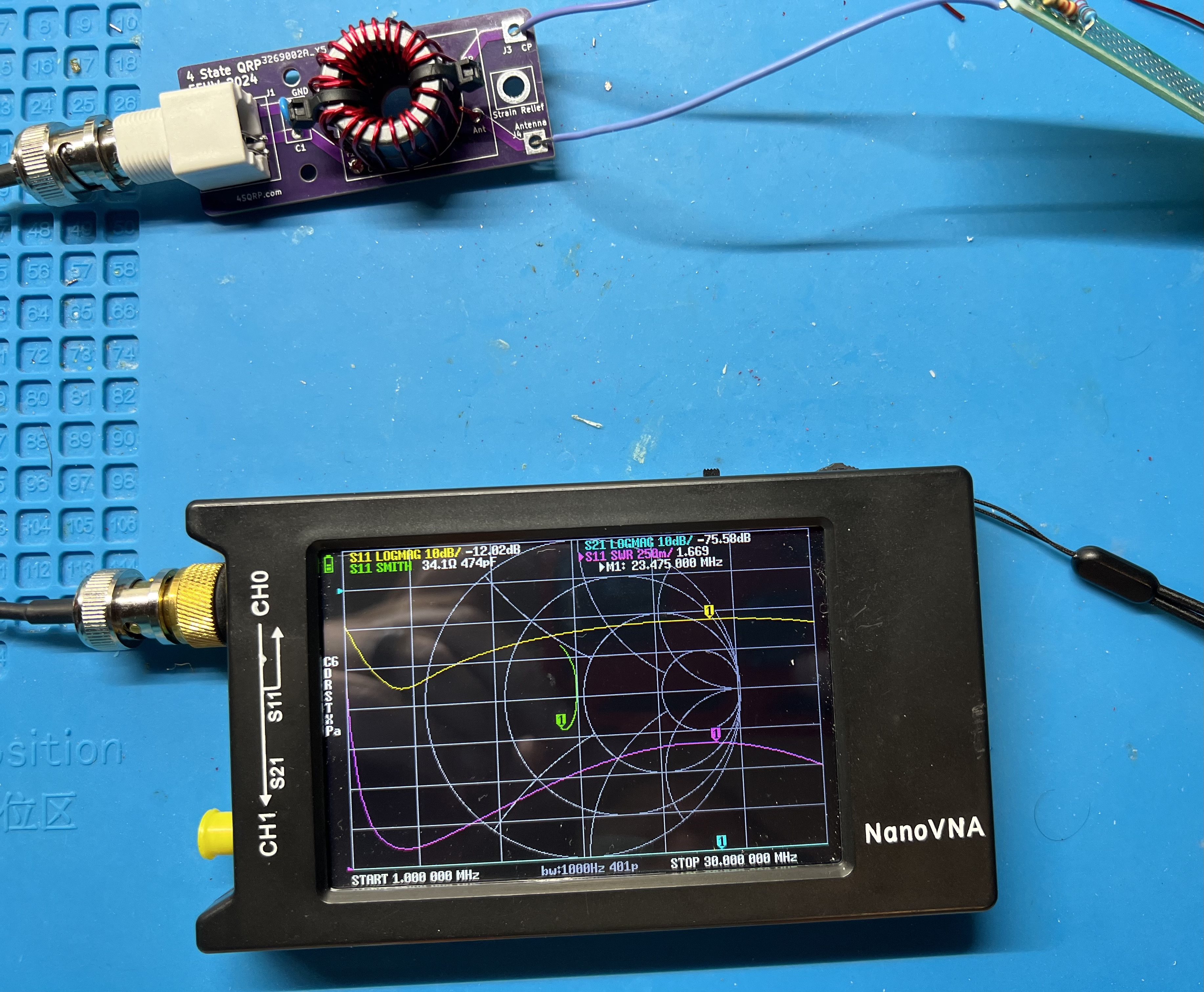
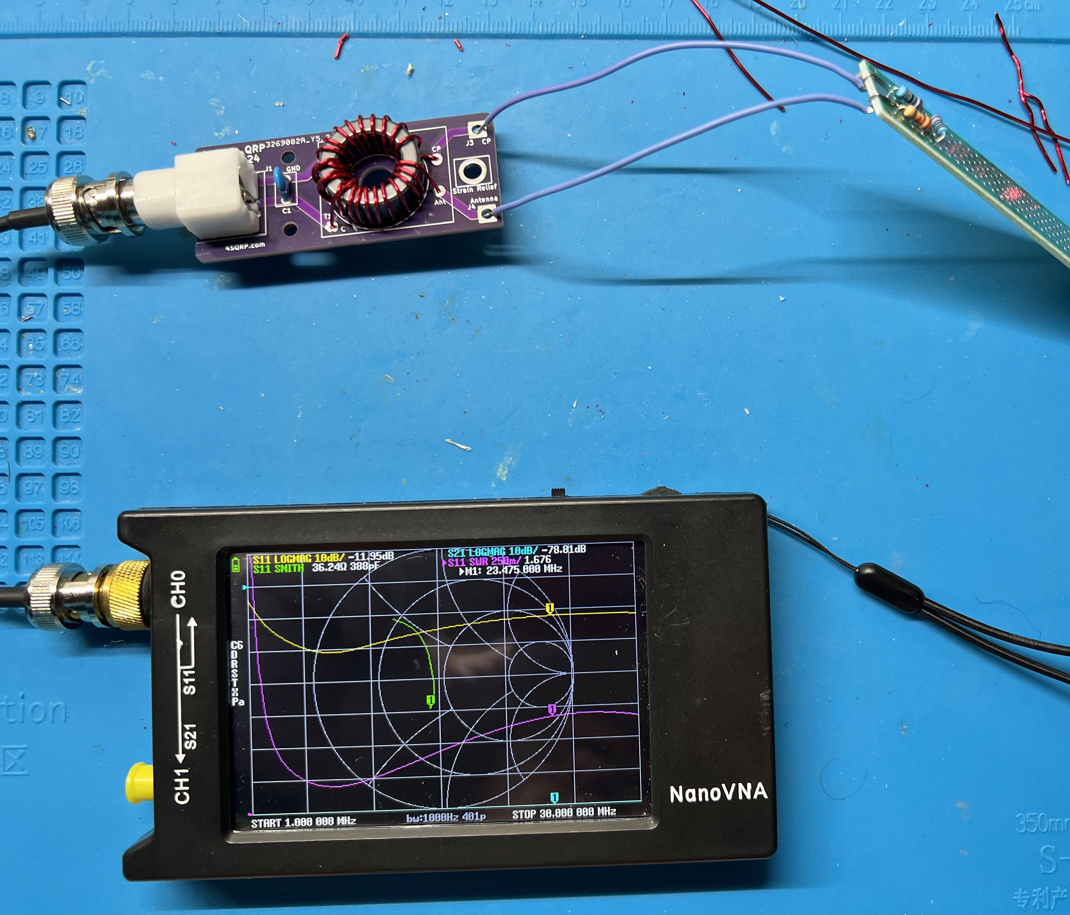
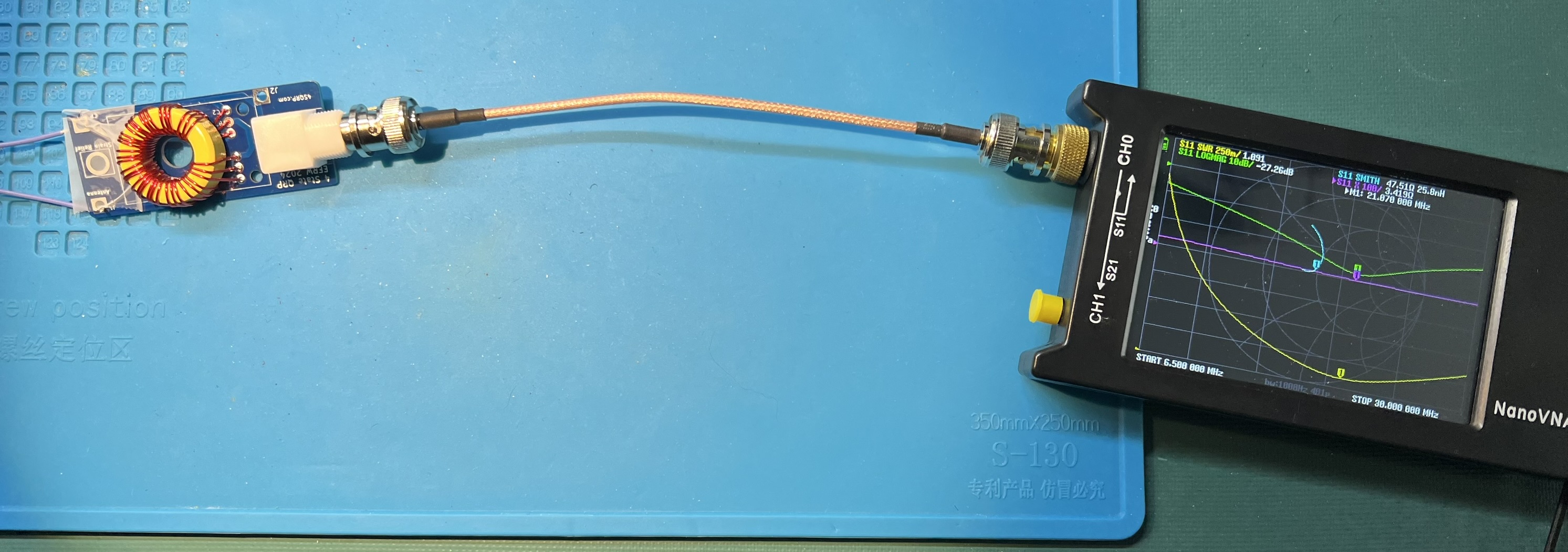
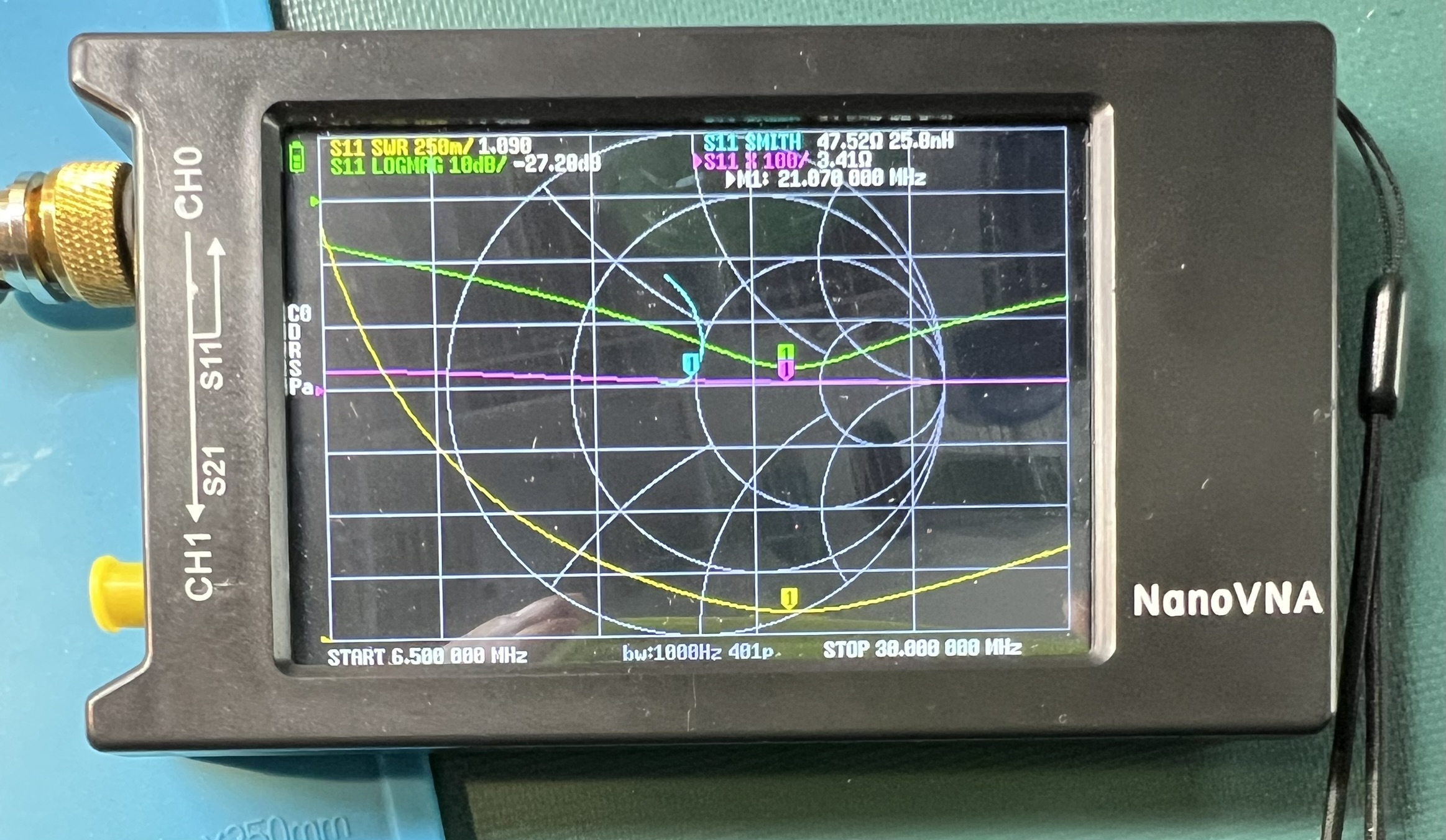
Transformer with a resistive test load and a nanoVNA showing SWR plot. Transformer with nanoVNA Transformer with nanoVNA

Single Toroid

Use 20awg enamel coated wire. Use the same assembly approach as with the double stack. However, with a single toroid, the Primary has 4" of wire, and the secondary uses 20" of wire. The twisted section will be a bit over 3" in length.

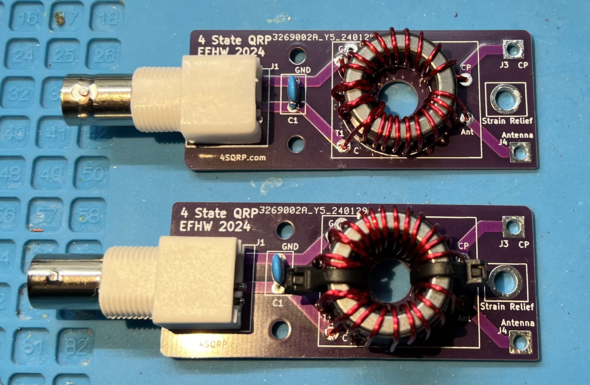
Single and Dual from above Single and Dual from above

Single and Dual at an angle Single and Dual at an angle

Shared Ground

Uses the same lengths of wire for single or double stack configuration.

Prepare the wire ends. 1 prep wire ends 1 prep wire ends

Slightly offeset the end of the twisted pair. 2 slightly offset twist 2 slightly offset twist

The twisted section will be a bit over 3" in length. 3 twist 3 twist

Wind onto the core in a counter-clockwise fashion. 4 wind counter clockwise 4 wind counter clockwise

Cross over the core at turn 11. 5 crossover at 11 5 crossover at 11

Remove the enamel from the wire where it will be soldered. 6 wound prep ends 6 wound prep ends

Solder the primary side wires. You will also solder the ground side of the secondary at this time.

Make a wire jumper to connect from the G pads in the toroid block over to the CP pad. You may consider soldering this ground jumper in at the same time as the primary and secondary grounds. I ended up soldering the jumper at the CP pad on both the top and bottom of the board. 7 solder shared ground 7 solder shared ground

Checking the completed board with a nanoVNA. 8 sweep check 8 sweep check

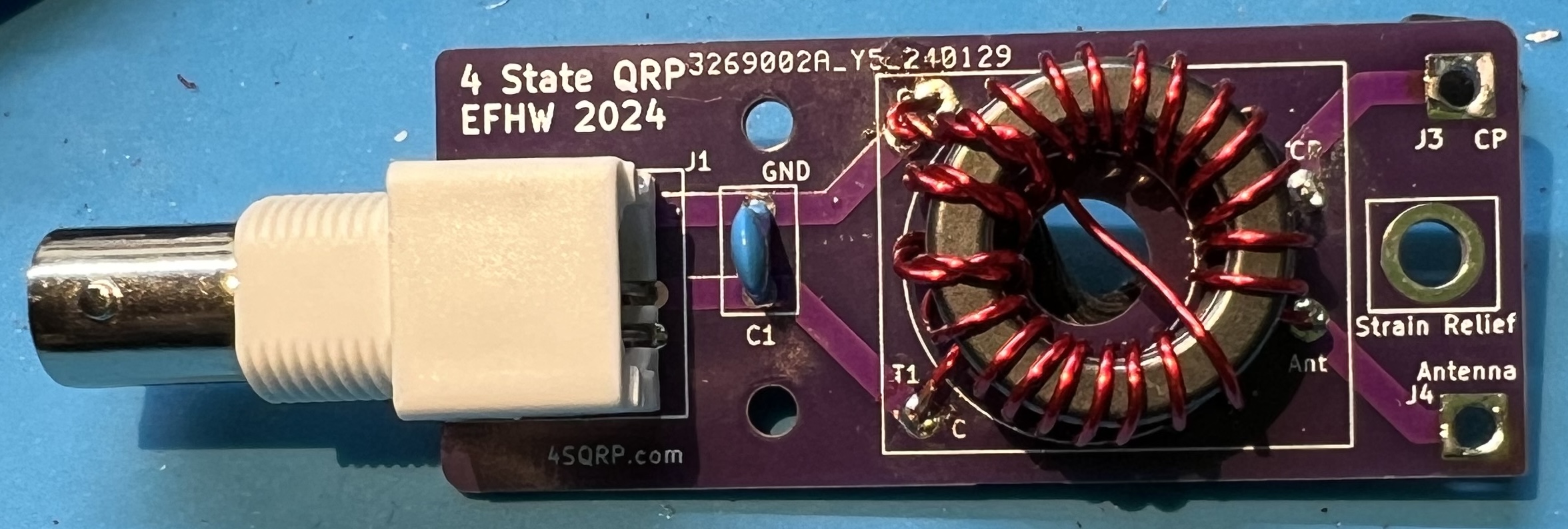
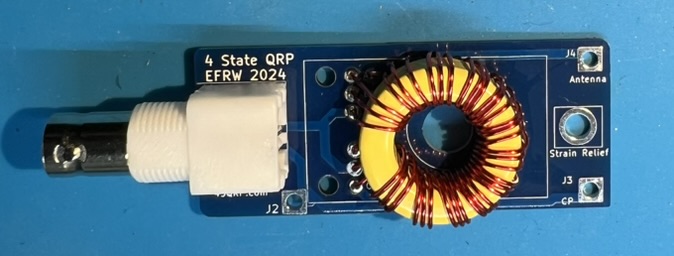
The completed board. 9 completed board 9 completed board

Theory

Windings

When you see a notation like 2:14 and 3:21 that means how many turns on the primary and how many turns on the secondary part of the transformer. 2:14 means 2 turns on primary, 14 turns on secondary. Likewise, 3:21 means 3 turns on primary, 21 turns on secondary.

So, where does the 49:1 come from? That is the transformation ratio. To arrive at it we consider the ratio of turns on the secondary to the primary. With a 2:141 this becomes 14 to 2 or 7 to 1. Take the 7 and square it to arrive at 49:1. We’re transforming a roughly 2450 ohm feedpoint down to 50 ohms.

Other common ratios that are used with EFHW antennas are 36:1, 64:1, and 81:1. Respectively ratios of 6:1, 8:1, and 9:1. To make a 36:1 transformer you could have a 3 turn primary, and an 18 turn secondary.

Note: In these pictures, they are all 49:1 transformers.

Original 4S QRP Experimenter PCB 2:14 Original 2:14 Original 2:14

Original 4S QRP Experimenter PCB 3:21 Original 3:21 Original 3:21

2024 EFHW board with Double Stack FT82-43 toroids, 3:21 Double Stack Double Stack

2024 EFHW board with Single Stack FT82-43 toroids, 3:21 Single Transformer Single Transformer

Transformer Theory

The 100pF capacitor is often added to the primary side of the transformer in an End Fed Half Wave (EFHW) antenna for a couple of reasons:

  1. Improves Higher Frequency UNUN Performance: The capacitor can help improve the performance of the Unbalanced to Unbalanced (UNUN) transformer at higher frequencies2,3.

  2. Compensates for UNUN Primary Leakage: The capacitor can help compensate for any leakage in the primary of the UNUN2.

  3. Flattens SWR at Higher Frequencies: The addition of the capacitor can help flatten the Standing Wave Ratio (SWR) at higher frequencies2. This is particularly noticeable for frequencies above 20 meters2.

It’s important to note that the specific impact of the capacitor can depend on the bands you are interested in. For instance, if you’re building an antenna for the 40m band, you might not need the capacitor. But if you’re also using the 20m band, the capacitor can be quite beneficial4.

Please note that these are general observations and the actual impact can vary based on specific antenna designs and operating conditions. It’s always a good idea to experiment and see what works best for your specific setup2,4.

Does the antenna system need a counterpoise? There is always one present. With end fed antennas you also need to watch out for common mode current (CMC) on the feedline.5

Primary Source: Conversation with Bing, 3/20/2024

Antenna Length

An end fed half wave antenna is a half-wave length long and is fed from the end as the name implies. So, determine your wire length by first considering the lowest band you want to work on. For example, 40m, or around 7.030Mhz. Then use the standard dipole formula of 468 / frequency = feet. So, for our example, 468 / 7.030 = ~66.57ft or ~66 feet and 7 inches. As the adage goes it is easier to trim wire than add it. Therefore, I would start with ~70ft of wire and adjust back from there. A simple thing to try is to fold the wire back on itself at the end.

The normal dipole like radiation pattern for the EFHW is when it is being used on it’s primary band. You will have more lobes on the usable or harmonic bands. With more lobes the further you get from the primary band.

You will most likely need to use some small amount of tuning when using the antenna portable or on non-primary bands.

Primary Band Usable bands Initial length
160m 80m, 40m, 20m, 15m, 10m 265'
80m 40m, 20m, 15m, 10m 135'
40m 20m, 15m, 10m 70'
20m 10m 35'

  1. https://noji.com/hamradio/pdf-ppt/noji/Noji-Article-80-10-EF-HW.pdf “80-10 end-fed half-wave antenna with 49:1 unun - Noji.” ↩︎

  2. https://www.ai6xg.com/post/efhw-xfrmr-capacitor “End Fed Half Wave Antennas: Is a Primary Capacitor Really Needed?” ↩︎ ↩︎ ↩︎ ↩︎ ↩︎

  3. https://www.ai6xg.com/post/end-fed-half-wave-antennas-more-about-the-primary-capacitor “End Fed Half Wave Antennas: More About the Primary Capacitor.” ↩︎

  4. https://dxexplorer.com/49-1-impedance-transformer/ “49:1 Impedance Transformer for EFHW Antenna - DX EXPLORER.” ↩︎ ↩︎

  5. https://www.radio-stuff.com/post/do-i-need-a-counterpoise-for-your-efhw “Do I need a counterpoise for my EFHW? - M0VUE” ↩︎

2024 EFRW Transformer

Completed board Completed board

Components

  • Bare PCB
  • BNC connector
  • Toroid T94-6
  • 48" of 22AWG enamel coated wire

Tools

  • flush cutters
  • mini pliers
  • utility knife
  • ruler
  • soldering iron, set to 350C
  • spudger
  • heat safe work surface (or board holder)

Instructions

bare board bare board

Winding the toroid

We will construct a 12 Turn trifilar winding.

  1. Cut the enamel coated wire into 3 equal lengths of 16". These will be your winding wires.
  2. Take one length of wire, bend it in half to create a U shape.
  3. Hook this U shape over the toroid to start your winding.
  4. Wind each half of the wire around the toroid.
    • Each pass of the wire through the toroid counts as 1 turn.
    • You want 12 turns around the toroid with each wire.
    • Be careful to not scrape off enamel coating when pulling the wire through the toroid.
    • Press the wire tightly against the toroid.
  5. Repeat the above process for each of the two remaining wires.
    • These wires should be wound between the turns of the previous wire(s).
    • Do not cross the wires over each other. Each wire should have its own separate, parallel path around the toroid.
  6. Once all wires are wound, double-check your work. You should have 12 turns per wire, for a total of 36 turns.

Testing and soldering the toroid

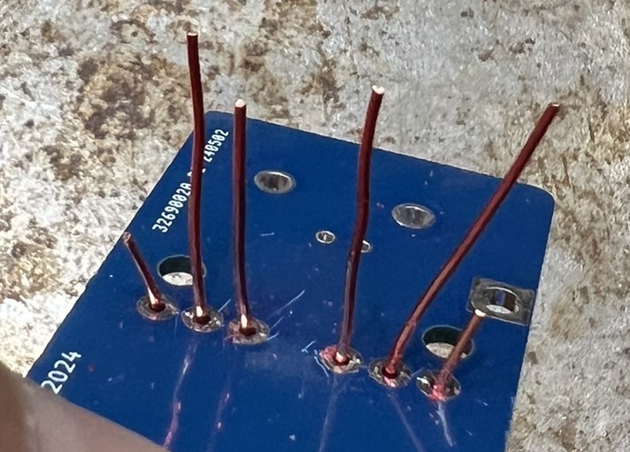
Wires through the back of the board Wires through the back of the board

Construction and testing:

  1. Feed the ends of the wires through A1, B1, C1, and A2, B2, C2 on the other end. DO NOT TRIM the wires yet!
  2. Remove a bit of the enamel from the ends of the wire. Where the wire is NOT in contact with the through hole it is passing through.
  3. Use an ohm meter to check that you have continuity between A1 and A2, B1 and B2, and C1 and C2.
  4. Now, carefully trim the wires, and remove enamel so that the wires will contact the through holes.
  5. Solder connections.
  6. Test continuity from BNC center to J4 - Antenna.
  7. Test continuity from BNC ground to C1 and J3 - CP.

Note: the spudger can be used to evenly space the wire around the toroid.

BNC

  1. Solder the BNC to the board.
  2. Check the transformer with a nanoVNA and 450 Ohm resistor.

transformer connected to nanoVNA transformer connected to nanoVNA

Subsections of 2024 EFRW Transformer

Theory

Windings

Why a 12 turn instead of a 9 turn? Because of inductance. 9:1 transformers designs are typically presented with T106 or larger transformers. Using the calculator at https://toroids.info I was able to determine that the amount of inductance for 9 turns around a T106-6 is 0.94uH. To approximate that amount of inductance with a T94-6 takes 12 turns to get 1.01uH. The transformer was markedly better with 12 turns versus 9.

close up of nanoVNA close up of nanoVNA

Transformer Theory

I like the diagrams on M0UKD 9:1 page. The first shows the physical aspect of the trifilar wound transformer. The second shows the circuit that is being implemented.

Like the EFHW transformer, there is ratio of turns in the primary versus the secondary. In this case we have 3 times the primary in the secondary. Thus it is a 9:1 transformer.

This transformer steps down a 450 Ohm impedence to 50 Ohms.

Antenna Length

The random in end fed random wire antenna is a misnomer. In order for the antenna to work, you must avoid half-wave lengths.

Antenna Length CP Usable bands
34’1, 41’, 58' 13’, 17' 40-30-20-17-15-12-10
71’, 84’2 17’, 33' 80-40-30-20-17-15-12-10

1 34’, 35’, and 35.5’ are commonly used lengths.
2 84’ antenna with a 17’ counterpoise is a W3EDP antenna.

Resources

Subsections of Morse Code

Learning Morse Code by the Koch Method

Using the SuperMorse Software Package
(Based on SuperMorse Version 4.04)

Copyright (C) 1994, Dave Finley, N1IRZ

The SuperMorse software package is an excellent tool for implementing the Koch Method of learning Morse Code. The prime attribute of SuperMorse for this lies in its tremendous versatility. Here is how to use SuperMorse to learn the code by the Koch Method.

When you get SuperMorse installed on your computer, take the time to print out the manual, read it, and become familiar with the features of the software. However, while reading the manual, remember that you are not going to follow SuperMorse's own training regimen but rather are going to use Koch's much more effective method.

Setting the Sending Speed

The Koch Method is based on teaching high-speed copying from the start. You must set the speed at which you want the software to send. There are two major considerations here. First, you want the characters sent at a rapid speed -- at least 18 wpm, and preferably at 20 wpm. Second, you want the overall sending and word speeds to be somewhat higher than those you will encounter in your exam, to give you a "buffer" against nervousness, unfamiliar surroundings, etc., on test day.

Set the speed in the following manner:

  • While the Main Menu is displayed, use the Function keys (F2, F4, F6, and F8) to increase the current speed to 15-20-15 if you intend to take the General/Advanced code test, or 20-22-20 if you're going for Extra. (You'll increase it some later for the Extra exam.)

  • Enter the Setup menu.
  • Press A to enter the "Code" subdirectory.
  • Press E to change Favorite Speed. This will set the Favorite Speed to the current speed.
  • Leave this menu, using the Escape key.
  • At any time, you may then Press Alt-F to set the current sending speed to this Favorite Speed.

Testing and Adjusting the Actual Sending Speed

The software is supposed to automatically calibrate its sending speed to adjust for the clock speed of your computer. However, it doesn't always do this accurately. In order to avoid the nasty surprise of finding that you haven't been copying as fast as you thought, you must check the sending speed. Here's how:

  • Set the code speed to the "Favorite" speed you will use in your training sessions.

  • Enter the Setup menu.

  • Press the C key to start the calibration test. The computer will send the word PARIS the number of times that, if the calibration is correct, should be sent in 60 seconds. At the end of the test, the machine will tell you how long it took to send the "60-second" test, and whether to increase or decrease the Timing Factor.

  • If adjustment of the Timing Factor is required, press the B key and change the Timing Factor as recommended.

  • Repeat the calibration test, using the C key. You may have to go through this cycle several times to arrive at the correct Timing Factor. Also, if you later change any of the sending speeds, you should check the calibration at the new speed.

Configuring the Character Set

This is where SuperMorse really makes itself invaluable for implementing the Koch Method. With this feature, you will tell the software exactly what characters from which it may choose when it sends. Initially, you'll start with only two characters, then add more as your copying accuracy increases. Here's how to do this:

  • Enter the Setup menu.
  • Press A to enter the "Characters" submenu.
  • Press the O key to clear all characters.
  • Press N for "Type."
  • Press the two keys for your first two characters (See Appendix). Those two now are activated.
  • Press the Escape or P key to leave the menu.
After you can copy those first two characters at 90 percent accuracy, you will repeat this process to activate your third character, then again for your fourth, and so on.

Now, It's Down to Business

With your speed selected and calibrated and your character set defined, you now can start learning the code!

  • From the SuperMorse main menu, press the B (Build Speed) key.

  • With the Koch Method, you're going to be receiving random groups of characters, instead of words or sample QSOs, until you are in the final phase of your training. Press A for Groups. SuperMorse offers three selections for this -- the R key for Random Groups of 5 characters each or the V key for Variable Length groups. The V key for Variable-length groups is your best choice. If you learn with 5-character groups, it will take extra time later on for you to adjust to copying words, which are, of course, of variable lengths.

  • SuperMorse will send for a specified time -- choose about 5 minutes. SuperMorse will begin sending the groups. Do not look at the screen, but copy on paper the characters sent by your computer. If you write in a relatively normal size on an 8.5 x 11 inch ruled sheet, such as notebook paper or short legal pads, you should get about five minutes' worth of code at 15 wpm on one sheet of paper.

  • When SuperMorse stops the timed session, stop copying and press the Escape key to remove the menu from the screen. Without touching any other key, compare your copy sheet to the computer screen. Count the number of characters sent and the number you copied correctly. If your score is less than 90 percent, keep working with the characters already activated. If you copied accurately 90 percent or more of the transmitted characters, congratulations! Add another character and continue.

After you've learned a few characters, say five or six, in this manner, enter the Review menu and press the E key to look at your statistics. Because you're not using SuperMorse's own training technique, most of the statistics will be blank. What you're interested in, however, is the total elapsed time of all your sessions with SuperMorse. By dividing the elapsed time by the number of characters you currently are copying accurately, you will find out approximately how much time it is taking you to learn a character. This will give you a rough idea of how long it will take to learn all 43 characters on the amateur test.

Keep in mind, however, that you will have good and bad days, and some characters may be more troublesome than others. Still, you should see steady progress as you add characters at regular intervals. Remember that as you learn each character by the Koch method, you are learning it at full speed.

When completing a session with SuperMorse, always exit the software using its menu commands. This will save all your settings and update your user file so you can better evaluate your progress. If you simply turn off the computer, your settings and user statistics will not be saved.

When you've learned all the characters

Once you've learned all 43 characters, it's time to make the transition from copying random characters to copying words. This will require some time, because random groups and words have a different character mix and "rhythm." If you've been copying variable-length random groups, the transition should be easier than if you've been copying 5-character groups.

From SuperMorse's Build menu, you press the B key to have words sent to you. There are further choices to be made here, though. SuperMorse will send "regular" words, "ham" words or callsigns.

Start out with "regular" words. When you have made the transition from random groups and are copying the regular words at 90 percent or better, start doing some sessions using the "ham" words and callsigns. You may want to spend some extra time with callsigns prior to the final phase of your training.

That final phase is to have SuperMorse send you a sample amateur QSO, which is exactly the format of the amateur code test. This also is done from the Build menu. Simply press Q for QSO, and copy the QSO. When it's over, grade yourself, taking particular note to ensure you are copying the callsigns, names, QTHs, rigs, ages, and other facts on which you could be tested.

When you are consistently copying SuperMorse's QSOs accurately at the target speed, you're ready for the exam. When the exam comes, just relax and do what you're accustomed to doing -- copying correctly.

Appendix:
In what order should I learn the characters?

First, remember that, for amateur tests, you are responsible for knowing 43 characters -- all the letters of the alphabet, the numerals 0 through 9, period, comma, question mark, slash, and the prosigns BT, AR, and SK.

You don't want to start with E and T -- the two shortest characters will come at you so quickly you'll wonder if you ever will copy them!

Over the years, researchers have made lists ranking the Morse characters in order of their difficulty, based on errors in copy. Other researchers, however, have showed that the characters missed most in copy are those least used, and that the "difficult" ones are copied quite accurately when they receive as much attention in training as the others.

The Koch method seems to largely overcome this problem in that you spend the amount of time necessary to assimilate each character before adding another to your training sessions. Still, it appears useful to mix long, "hard" characters and short, frequently-used ones rather equally as you progress.

Based on this idea, here is a suggested sequence:

          K M R S U A P T L O
W I . N J E F 0 Y ,
V G 5 / Q 9 Z H 3 8
B ? 4 2 7 C 1 D 6 X
<BT> <SK> <AR>

So you want to learn morse code

How to Avoid Frustration, Minimize the Pain
And Gain Full HF Privileges


By David G. Finley, N1IRZ
Copyright (C) 1995 All Rights Reserved*

Most of what you've been told about learning Morse Code is wrong -- dead wrong. Amateur radio operators traditionally have used the slowest, most frustrating, most painful and least effective techniques possible for gaining code proficiency. It's no wonder that the 13- and 20-word-per-minute requirements for full HF access are considered a nearly insurmountable barrier by many hams.

You can overcome that barrier. You can do it in a reasonable amount of time and with a minimum of frustration and pain. In order to do so, you must approach code training from a different perspective and use different techniques from those common among amateurs for the past half century.

It will require work. You will have to commit yourself to at least one 15-30 minute training session every day until you reach your goal. You may succeed in a month or in several months; individuals differ greatly. Without this committment, however, you may as well not bother.

So what's new here? By using a code training method devised by a psychologist some 60 years ago, you will progress as quickly as you possibly can, with ample reinforcement and little frustration. By understanding this method and how it builds your code proficiency, you will know why you have to spend time practicing and you'll be able to make a reasonable prediction of how long the total effort will require.

We're going to start on your road to success by throwing some time-honored ham-radio traditions onto the trash heap where they belong. These are:

  • Slow (5 wpm) code -- It ought to be illegal to teach anyone code at 5 wpm. Every minute spent toying with 5 wpm code is irrevocably wasted. In addition, as we'll see later, starting with slow code is a virtually-guaranteed path to frustration and quitting. Morse at 5 wpm and Morse at 15 or 20 wpm are completely different critters, and you don't want to waste time on the wrong one.
  • Charts, mnemonics, musical cues and other "memory aids" -- These things make you think about what you're doing while trying to copy code. That is deadly to proficient copying.
  • Code tapes -- In very short order, and unconsciously, you'll memorize the tape. This will lull you into false confidence in your ability. That false confidence will be quickly shattered when you hear transmitted text that you haven't memorized.
  • Copying QSOs off the air -- You don't know the speed of code you find on the bands, and much code on the air is pretty badly sent. All this makes it useless for training purposes.

Now that you know what you're NOT going to do, let's start examining just how you can best gain code proficiency.

The Mechanics: Just what is code training, anyhow?

Go to the shack of a veteran CW operator, or visit the CW station at a club Field Day operation. Watch people copy and send code at 30 to 35 wpm. You'll notice they're pretty relaxed about it; they're not sweating each character as it comes out of the speaker and they're not racking their brains to "figure out" what's being sent. Code has become second nature to them.

That's the key to code proficiency. Copying code must be a thought-free process. When you hear a character, you should know, without thinking, what it is. It should be a REFLEX. In fact, copying above about 10 wpm can only be done by reflex. Above that speed, thought processes are too slow to succeed.

That's why slow code is a deadly trap, and why traditional amateur methods of code training are so painful and frustrating. Most hams are told to memorize all the characters, then start building their speed. When you do it this way, you build a "lookup table" in your brain, comparing each character you hear with those in the lookup table until you find a match. This process shuts down from overload at about 10 wpm. That's why people experience a "plateau" at 10 wpm, and don't see any progress for weeks or months.

Those who finally get over that "hump" and progress beyond 10 wpm do so because, through constant practice, they have begun to copy code by reflex instead of by thought. They are the lucky ones; this 10 wpm barrier is where many folks give up out of frustration.

Code training, then, should completely bypass the lookup-table phase and begin by building copying proficiency as a reflex. This was recognized in the 1930s by a German psychologist named Koch, who devised the most efficient method known for Morse training. It's his method, and how you can use it, that we're going to examine in detail.

Morse Training by the Koch Method

Koch's method is a simple, direct way of building reflexes. However, it requires either a computer and Morse software or a personal trainer. That's why it was overlooked for so many years. Now that computers are commonplace, it should become the standard Morse training method. Here's how it works:

You start out by setting up your computer to send you Morse characters at 20 wpm and at an overall sending speed of at least 15 wpm. You then get out your paper and pencil and have the machine start sending -- but only two characters. That's right, for your first sessions, you'll only have two choices. Copy on paper for five minutes, then stop the machine and compare what you copied with what the machine sent. Count characters and calculate your percentage of correct copy.

If your score is 90 percent or better -- congratulations! You just learned your first two characters, and, importantly, you learned them at full speed. You'll never have to learn them over again. If you didn't make 90 percent, practice some more. As soon as you can copy the first two characters with 90 percent accuracy, add a third character to your practice. Your accuracy will drop as you work on assimilating the new character, but it will rise again to 90 percent or better. Then you add the fourth character, and so on.

This method does not allow you to build that lookup table in your brain. To copy at full speed, you MUST build the reflexes in order to achieve 90 percent accuracy. And that's what you're spending your time doing -- building reflexes. Think of it as a parallel to perfecting a tennis swing or mastering a gymnastic routine; you're practicing until you get it right. The Koch method of building code proficiency character-by-character is similar to standard methods of teaching touch typing, another skill that must be reflexive.

This is a very individual method of training -- you progress at your own best speed, and spend only the time required to gain each new character. This means that you will waste no time in reaching your goal.

How much time is required? That will depend on the individual. Koch himself, with hand-picked students, got a group to master 12 wpm code in a mere 13.5 hours. You probably won't match that, but that's much faster than any other method in the psychological literature. You can get an idea of how long it's going to take after you've mastered a few characters. Keep track of your training sessions (some software will do this for you) and calculate your hours-per-character rate (or characters-per-hour if you're really fast!). That, multiplied by the 43 characters in the amateur Morse test, will give a rough idea of how long it's going to take.

While the Koch method is the fastest method of Morse training, speed alone is not its principal advantage. Its principal advantage, and a major difference from other methods, is that it provides you with constant positive reinforcement. This begins with your realization, after mastering the first two characters, that you CAN copy code at 15 or 20 wpm, because you just did it. After that, each new character mastered is further proof of your progress. Contrast that to slowly trying to build speed up from 4 or 5 wpm, then hitting the plateau at 10 wpm and seeing no progress for a long time. With the Koch method, frustration is at a minimum.

Constant testing is necessary to ensure that you maximize the effectiveness of the Koch method. You must copy on paper, so you can grade yourself. Remember, if you score 90 percent accuracy or better, add another character. If you score any less than that, try again. By constantly testing yourself on continuous copying of at least five minutes, you know exactly how you're doing and exactly when you should add another character. This results in the fastest progress possible.

Naturally, with the Koch method, you'll be copying random groups of characters, rather than words, until you've mastered the entire character set. If your software allows, make these groups of random length, rather than a constant stream of five-character groups. This will ease the transition from random groups to actual words. Yes, there is a difference in the rhythm and "feel" of words and random groups. Once you've become accustomed to copying words, you should start copying sample QSOs, which are the format of the amateur tests. Pay special attention to callsigns, locations, and numerals; these are the types of things that can form questions on the test.

As you proceed toward your goal, remember that some days are just going to be better than others and some characters will take longer to assimilate than others. You know, however, that you can reach your goal because you've already mastered some characters and proven that copying at full speed is something you can do. Keep in mind that what you're doing is building reflexes, and that takes time. The amount of time you require has nothing to do with your intellegence; it's just how long it takes for characters to "sink in" and become part of your reflexes.

So there it is -- your path to passing the 13- or 20-wpm code test. After you've used this method, and start enjoying the wonderful world of HF radio, try a few CW QSOs. With Morse code developed as a reflex, you may just find that you really enjoy using it on the air. After all, you've gained proficiency without the frustrating ordeal that most hams have endured for decades. See you on the HF bands!

Bibliography

Finley, D.G., "Reducing the Barrier: Effective Morse code training," Radio Fun, May 1995, pp. 14-15.

O'Keeffee, V., "Learning Morse," QST, August 1972, pp. 58-62.

Peak, H., "Koch's Method of Learning Code Reception," Psychololgical Bulletin, XXXIX (1942), p. 495.

Taylor, D.W., "Learning Telegraphic Code," Psychological Bulletin, XL (1943), pp. 461-487.

Taylor, D.W., "The Learning of Radiotelegraphic Code," American Journal of Psychology, LVI (1943), pp. 319-353.

Instructions for implementing the Koch method with Super Morse V4.04 software.


A Personal Note

These ideas may sound very bold and unconventional, but I know they work, because they worked for me.

I fell in love with radio in grade school, but was kept off the air for 30 years because I found traditional code training just too frustrating. During those decades, I tried several times to learn Morse, but every time gave up in frustration and disgust -- my progress was just too slow.

In 1991, I became one of the first 500 people to enter ham radio by way of the no-code Technician license. After becoming bored with repeaters and HTs, I decided to make one last attempt to master the code. Fortunately, I stumbled on information about Koch's method, and found that it was the only thing that would work for me. In 1993, after diligent work at my computer, I took my first code test and passed the 20 wpm exam on the first try.

I became very curious about why Koch's method had worked for me when all else had failed. That sent me to libraries to read the now-aging psychological literature about Morse training. I soon realized that the Koch method achieves its speed through directness; if you want to copy reflexively at 15 or 20 wpm, then just start building those reflexes from the start. I also realized that it provides much more positive feedback than any other method, so you can keep your motivation and a "can-do" attitude throughout your training.

This was knowledge I wanted to share with others, so I began giving lectures to amateur groups on the topic. I quickly found that, after my lectures, "old-timers" would come up and tell me that my ideas on the need for reflexes were absolutely right. Many said that the Koch method sounded similar to the intense code training they had received in military schools.

Probably the only reason Koch's method didn't become standard back in 1936 when he first published it was that the average individual had no way of implementing it. The personal computer has changed that, and the time has come for the Koch method to replace all others. I hope that the speed and positive-reinforcement aspects of the Koch method can cut down the code barrier to a much less formidable size.

Sometime during 1993, those who have not passed at least a 13-wpm code test became the majority of radio amateurs in the United States. While the debate over the code requirement continues to rage, I hope that use of the Koch method can help many more people overcome the barrier and enjoy full HF privileges right now, instead of several years from now when the requirement may be lifted.

I cannot overemphasize my dislike -- even hatred -- for 5 wpm code. As I've outlined above, it is highly counterproductive to gaining proficiency at higher speeds. In order to go from 5 to 13 wpm, you have to start over again, even though you may not realize that while you're doing it. The worst aspect is that many people pass a 5-wpm test, then never go beyond that. They are trapped in the ghetto of the Novice/Tech HF bands. Why waste your time learning a skill (slow code) that has no relevance to real (13+ wpm) code proficiency? Why limit your HF operating to the most unattractive parts of the amateur bands?

Finally, as I was using the Koch method and building my code skills, I intended to forget the code as soon as I passed the test. My 30 years of frustration had built up a bitterness about CW. However, about two weeks after getting my first HF rig on the air, I looked at my straight key and decided to try a CW QSO "just so I can say I did it." Guess what? I enjoyed it. My second CW QSO was with a DX station, and I was hooked. With the encouragement of a CW Elmer, I continued to enjoy the bottom parts of the bands, and now my microphone isn't even plugged into the rig!

If the Koch method could overcome three decades of bitterness and turn me into an enthusiastic CW operator, I think it's certainly worth a try on your part. Have a go at it. Maybe I'll find you on the CW bands and we can have a ragchew.

Best of luck, and 73.

Dave Finley, N1IRZ

* This article is copyrighted by the author. Permission is hereby granted to transmit and distribute it by electronic means and to store it on electronic bulletin board systems, and for individuals to download and print copies for noncommercial, personal use, provided that the article is transmitted, stored and printed unaltered and in whole, including this notice. For any other use, written permission from the author must be obtained.

Subsections of Operating Activities

Subsections of POTA Kick Start

1 - Prep

Things to do before heading to the field.

Parks On The Air Specific

Get a POTA account set up

POTA Cognito Signup

Familiarize yourself with the Parks On The Air program rules

Check out the POTA YouTube Becoming an Activator playlist

Park Research

Scope out your park. Use the website to determine if the park you are interested in is in the POTA program.

POTA planning your activation video

Research the park rules and park events.

Do a recon trip or reach out to previous activators.

A successful activation

10 contacts makes for a successful activation

Before going into the field, write the following in your log book: park name, park number, grid square, county, and state.

Alerting and Spotting

Alerting is I’m going to be at this park, I think I’m going to be active during this window (UTC), and I’ll most likely be using these band/mode combination.

Spotting is I’m activating now! Right now, I’m at park #, on frequency, and operating mode.

To post an alert or spot, first open the pota.app website. Then login. Next you will user the hamburger menu to select to add an Activation or a Spot.

The community

You can find POTA enthusiasts online: Facebook, Slack, Discord, Instagram, YouTube

Operating Portable

Building a POTA station video

Essential Gear

  • Copy of your FCC License
  • Transceiver
  • Antenna
  • Power Source
  • Key / Mic
  • Logbook and pen or pencil

Supporting Gear

  • Memory keyer
    • Long CQ: CQ POTA CQ CQ DE callsign callsign K
    • Short CQ: CQ POTA DE callsign K
    • End QSO: 72 callsign
    • Park Identifier: park identifier
  • Coax, cord, throw weight, back pack, mast, tripod, …
  • Shade tarp
  • Digital audio recorder, camera

You

  • Know your limits - WX, etc
  • Food & Water
  • Buddy up?

Set up a QSO Map account

Go to the QSO Map site. Then on the menu bar, Account -> New -> Register

Logbook of the World

The ARRL does not have an affiliation with the Parks On The Air program. POTA does not require Logbook of the World log submissions. It is a totally optional activity for you.
It does take quite a bit to get LOTW set up. So, why do it? Do it for those hunters that are after you in order to complete ARRL awards. If you are going to use LOTW, take the additional step of creating a location profile for each park you activate.

2 - QRV

Setting up your station

Questions and ramifications to consider when setting up your station:

  • Will you be able to utilize a shelter?
  • Are you operating from your car?
  • Is there a bathroom facility nearby?
  • Is there potable water nearby?
  • Are you hiking in?
  • What natural hazards (critters, plants, terrain) do you need to watch out?
  • Are there other people nearby? Make sure your fun doesn’t yuck their fun or pose a hazard to them. Be prepared to answer questions. Maybe have an informational hand out ready.

Improving the station setup

Make note of any lacking equipment, or something that could have been useful. Address it when you are back at home. For example, an extra stake or s-biner would have been handy when hooking up a transformer. Or, the specific pen/pencil being used didn’t work well. Swap it out.

Secondary Operation

Consider the following:

  • Beaconing your location with APRS
  • Keeping a radio on 146.52 for local 2m FM contacts
  • In areas with lots of traffic on 146.52, try 146.58 Adventure Radio Frequency

Antennas

The more you have in the air, the better off you are. Be aware of the locaiton rules and regulations. Some places are permissive and you’ll be able to get your wire up in a tree. Use an arborist line and throw weight. Do not use paracord or fishing line. They are not designed for use in trees and have a good chance of snagging or breaking. As ambassadors of the hobby we want to take care to follow leave no trace principles. Nice options for these locations are EFHW, “random” wire, and trapped vertical

Some locations like National Parks, and wild life refuge areas are very restrictive. For locations like that be prepared with an option that is self supporting and does not require any ground penetration. Good antenna options for locations like this could be: Elecraft AX1, AX2, QRP Guys DS1, Buddipole or BuddiStick, or Gabil GRA-7350TC.

Field logging

Paper logging

I typically paper log (Rite in the Rain notebook #73 size) with a pen or pencil. If you make a mistake, don’t try and erase it. Simply draw a line through it. The log book is clipped onto an A5 size clipboard. The clipboard also has an elastic band to help keep the journal page down in windy conditions. A small cord runs from the clipboard to the pencil. This makes for easy retrieval of the dropped writing implement.

Logging

Logging your activation for POTA Video

Have your Park name and number handy. You may occassionally be asked for your county, state, or grid square.

What should I log? Log Band, mode, UTC Date Time, Station worked, Report sent, Report received, State|Province|Country received.

Write down the band, mode, and UTC time on a line. Then on subsequent lines the UTC time (if there is time), call sign of the station worked, RST sent, RST received, and SPC received. When you work the last station in a run, or are getting ready to call CQ again, make sure to note the UTC time. Missing times can be “fuzzed” in later.

When changing bands make sure to note it in the logbook.

Audio Backup

You may optionally use a digital audio recorder to record your activiation. It can be helpful to have as a backup to your paper log. The model linked to can also serve as an audio level control for rigs that don’t have one. Get experience with connecting and using the recorder before you go into the field.

Operating tips

Common

Make sure you’re in a comfortable and safe position. Have your easily accessible drink nearby.

If you start to feel overwhelmed by a pile up or the pace of things, take a breath and remember, it is your show. You determine the flow and pace.

Use a band change as an opportunity for a bio-break or to hunt other parks.

Morse Code

  • Start at a faster wpm, then slow down
  • start with your filter wide, then narrow filter only as necessary
  • Listen for stations that are off zero beat, use RIT as needed
  • If you need a break to move to a new page in the log, etc, you can use the Morse code prosign AS along with a number X. This says, stations please stand by X minutes.
  • Hunters sending faster than you copy? Ask them to please slow down: PSE QRS

Working a pile up

If you have a large pile up, you may find it useful to call for specific stations:

  • QRZ P2P? Any P2P (Park to Park) stations?
  • QRZ QRP? QRP, portable, or mobile stations call now
  • CQ DX? DX stations call now
  • By the numbers (call district)
    • very rare are you running a special event station or some other highly sought after location?

Don’t do all of the above at once or maybe, at all. Most operators of QRP, portable, mobile, and DX stations realize that they will likely have a weaker signal. So, they will typically wait until the pileup has dwindled and then try to call you then.

Operating split

Operating split is a very rare occurrence with POTA. If you end up with a large group of hunters zero beat, try CQ UP. Then use your RIT or split feature to listen around 1Khz UP from your transmit frequency.

3 - Post

Post event activities

Log Processing

Logging your activation for POTA Video from QRV section

NOTE: The primary method for submitting your logs is to upload them using the website. However, you can still email them to your area coordinator.

Fast Log Entry

Since, we’ve paper logged, we’re going to post process with Fast Log Entry on your Windows laptop. On your Linux Laptop we’ll use FLEClient.

ADIF Master

Check your ADIF file with ADIF Master A common problem is the use of the letter O versus the number zero.

QSO maps

See where you worked by creating a polylines map with QSO Map

  • Start by uploading the ADIF file from your activation
  • The site will send you an email of what stations have been added to your log along with callsigns that it didn’t recognize.
  • Check your log and files for the callsigns that weren’t recognized.
  • Hand waving - create a map, I like to use polylines and colors by band.
  • Use screen clipping tool to capture the displayed map.

Submit the log to POTA

With POTA, NO ONE gets credit until you turn in the log!

POTA log uploading This video was in the Activators video play list.

Filename convention: CallSign_K-####_ST_YYYYMMDD.adi where ST is the 2 letter state abbreviation. If you are in a multi-state park, use the state that you activated from within.

POTA documentation on submitting your logs

Submit the log to ARRL LOTW

First, set up a location in TQSL with your park info from above. Then submit your log for processing with the correct location.

Activation report

Share with your buddies, club, other POTA ops

social media: FB, IG, Slack, Discord

Improvements

Refer to your log and see if there were any station, kit, operating, or other improvements you noted.

72 - Bonus

This kick start guide has taken a very focused approach to get you going. Where can you go from here?

  • Try electronic logging in the field. This will also lead to a different way of exporting your log.
  • Or try using a spreadsheet program with CSV file along with ADIF Master to create your log
  • Try operating digital modes
  • Experiment with antennas
  • Try different bands
  • Can you utilize alternate power (solar, wind, water)?
  • How low can you go with your power, QRPp?
  • What does it take to operate at 20W, 40W, 100W, or more?
  • How light a station can you put together?
  • How can you operate from a vehicle in cold or hot weather?
  • Can you operate your station after dark?
  • Research the different ways of doing a multi-op activation
  • Can you bring a solar panel and charge controller into the mix to extend your operating time?

OzarkCon Event

Specifics for OzarkCon POTA Kick Start.

This event is for the QRP amateur radio operator that would like to get started with the Parks On The Air program.

Facilitator

Bryan, K0EMT, is your event facilitator.
Mike, AD0YM, will be assisting.

Homework

Before you come to OzarkCon:

Event

This is a two part day:

  1. The park activation during the day.
  2. Processing the logs in the evening.
    • After the banquet, in the hall

Morning

Gather at 10:00 AM local time at the Stone Castle Inn lobby.

We will then go to the shelter at Table Rock State Park.

Directions and map to the shelter

Evening

In the evening after the banquet we will gather at in the banquet hall to work on the logs.

Even if you complete your log on your own, please join us. I’ll be aggregating our totals for a report on Saturday.

Safety

This is a NO ALCOHOL event.

Weather

  • If there is ice on the ground, we will not activate
  • If there is lightning, we will cease operation.
  • If the wind chill is below 32F we will not operate
  • If the heat index is over 90F we will not operate

If we are not able to be outdoors, we will do an alternate activity at the hotel.

Personal

Make sure you bring proper hydration and snacks for your outdoor time. Temperatures this time of year can vary between 29F and 67F. Layering your clothing is a good idea. Know your limits, don’t push it. If you need help, ask for it. Keep an eye out for fellow activators.

POTA info

When operating, you will use your callsign. You need a minimum of 10 contacts to have a ‘succesful" activation. No matter, how many contacts you make, you need to submit a log.

Have your park name, park number, grid square, county, and state handy when you’re operating.

Table Rock State Park, US-1787, Taney County, Missouri, Grid Square EM36. NOTE: if you venture out further around the park, you may end up in Stone county.

Station

We will be able to have multiple stations operating at the same time.

Stations will:

  • Have an HF transceiver (or bring yours)
  • Be on different bands
  • Operated at QRP power levels
    • 5 Watts for CW
    • 10 Watts with phone
  • Have an antenna and coax (BNC male terminated)
  • a bandpass filter

There will also be a 2M FM station set up for simplex operation.

Field Gear

Essential Gear to bring:

  • Headphones or earbuds
  • paddle or key with 1/8" TRS plug

Optional Gear:

  • Your transceiver that has a female BNC antenna connector (or adapter)
  • A memory keyer (Program with long CQ, short CQ, 72 your callsign, park #)
  • Battery with Anderson Power Pole connectors
  • digital audio recorder with 1/8" TRS plug for transceiver side
  • A logbook, paper or journal and a pen or pencil
  • UTC time piece

Comfort:

  • Seat pad or outdoor folding chair
  • lap blanket

WQ5RP

We will likely be able to activate with the 4S QRP club, WQ5RP. More details on how that will be done are coming.

Log processing

Friday evening gathering will be in the banquet hall, after dinner.

  • We’ll get your logbook translated into FLE
  • Generate ADIF files
  • Create Maps
  • Submit log to Parks On The Air program
  • Set up LOTW location
  • Submit log to LOTW
  • Check out account on the POTA site
  • Do a happy dance

With POTA, NO ONE gets credit until you turn in the log!

Subsections of Operating Aids

K0EMT's Operating Aid

NIST Time

US WX Radar | Missouri ARES Interopability Plan | Mid-MO ARC Net SOP

ARRL Op Aid, Frequency Allocations, Band Chart


QRZ
WM7D US QRZ
Buckmaster Intl QRZ
RBN10m15m20m30m40m80m CW
Real-time HF Propagation chart
HF Radio Propagation site | Optimal Working Frequency Charts

Software Projects

Current Projects

See my GitHub repos for several current projects:

  • Generating POTA and SOTA logs
  • DMR Contact Lists

Obsolete Projects

Unfortunately, I believe these projects are probably no longer viable.

  • dxSpot Java based GUI to DXWorld.com which appears to be mostly off-line / defunct at this point.
  • QRZ Classes for VB and Access/VBA Seems like QRZ is no longer selling CDs. They have a web service interface now.
  • Radar Widget for Konfabulator. Konfabulator was bought and eventually decommissioned by Yahoo! It is my understanding that the software no longer functions properly on modern Operating Systems.

Subsections of Software Projects

DXSpot

This program is a java interface to the data at www.dxworld.com.
dxSpot is Copyright 2000 Bryan Nehl -- k0emt.

Command Frame Preview
Here is a snapshot of the 6M & 2M DX and QSO dxSpot windows on my Linux Machine. 200K
Here is screen capture of all windows open with CommandFrame. 481K

Features:

  • Minimizes bandwidth use, only reads up to point it last read.
  • Starts the window with the "look back" log.
  • Each frame is set to refresh at 5 minutes.
  • Frame updates upon QSO or spot submission.
  • The user may also manually force an update.
  • Can display HF/6 & 2M QSO & DX frames without requiring a bunch of screen real-estate.
  • Users grid & callsign are automagically appended to submissions.
    IF they are set other than MyCall and MyGrid.
  • User configuration
  • QRZ feature -- CommandFrame version only

Executing:

Method One - jar expansion

First get the dxSpot.jar.

Copy it into a directory on your computer called dxSpot.

Expand the jar file with: jar xf dxSpot.jar
Capitalization is important. The S is a capital.

run the program: java com.dbbear.dxspot.dxSpot
or for a more powerful command line style interface:
java com.dbbear.dxspot.CommandFrame

Make sure classpath directories, etc are set correctly.
You may need to invoke java or jre with the -cp (class path) option.
For instance, if you are in the directory where you unjarred the dxSpot classes:
prompt$> java -cp . com.dbbear.dxspot.dxSpot

Method Two - no jar expansion

Run the default dxSpot with the following: java -jar dxSpot.jar

Method Two - no jar expansion with config

Note that this approach switches to -cp and full class name to run

java -cp dxSpot.jar com.dbbear.dxspot.CommandFrame sample.config

Configuration File

You can specify a configuration file like this sample.config by passing the name of the file in on the command line.
for example: java com.dbbear.dxspot.CommandFrame sample.config

IMPORTANT:

Make sure to use <ENTER> key when entering Callsign & Grid in dxSpot.
A "successfully changed" message will display when you change either your Callsign or grid.

Source Code

Source code is available on GitHub.
Requires Java 7

QRZ Interface Library

Abstract License Details User Software Responsibilities Status

Abstract

This library gives the Visual Basic or Access 97/VBA programmer a class so that they may easily retrieve information from the QRZ CD.

License

The class and accompanying files are being distributed under the terms of the GNU LGPL with the stipulation that this author (K0EMT) is to receive a free copy of any commercial software that utilizes this library.

Details

QRZInfo Class Properties:

  • DBPath AS String - name of the directory where callbkc.dat is located
  • CallSign As String - call sign in "normal" format
  • qrzCallSign As String - call sign in QRZ format
  • qrzDEFCAB As String - call sign in QRZ "defcab" format
  • hasEMail As Boolean - has an email address on the cd - originally JR field
  • hasGif As Boolean - has a gif on cd - originally MI field
  • LastName
  • FirstName
  • ProperName (First Name + Last Name)
  • Street
  • City
  • State
  • Zip

Limitations:

  • The library only supports look up by callsign.
  • The class only returns if the email address and/or picture are stored. (Not the actual email address or picture.) To get the email address you will have to use the QRZ DLL.

User Software Responsibilities

The developer must remember to set the .DBPath of the class to the location of the QRZ callbkc.dat directory.

Status

As of May 2001, no further development on this interface is planned.
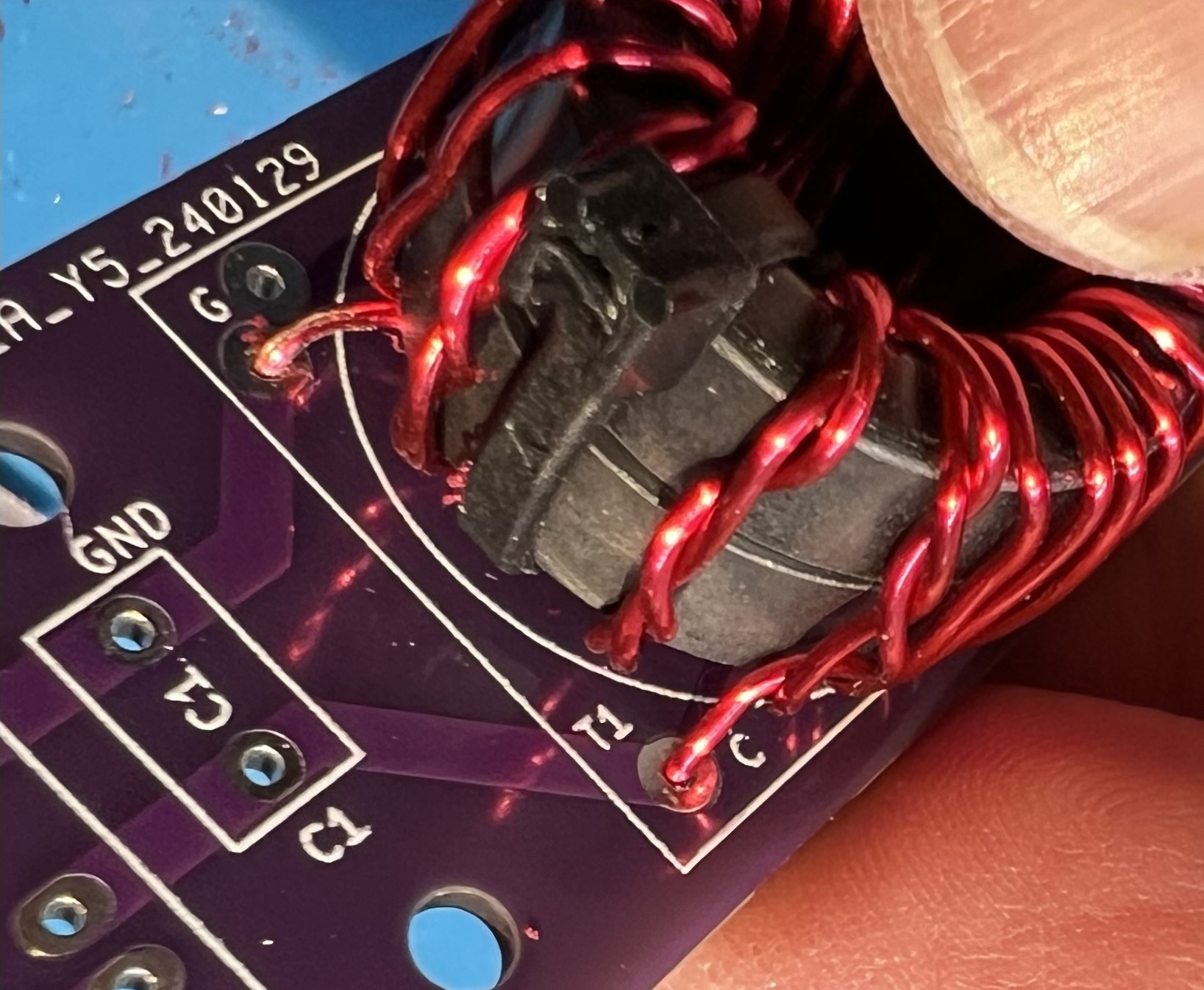
If you would like to add the following features:

  • Searching by other indices
  • Return the location of the associated picture
  • Return the email address
  • Additional error handling/checking

I would be happy to integrate them into the library and give you credit.

73 -- k0emt

Radar Widget

Abstract License Details User Software Responsibilities Status

Abstract

K0EMT's Radar is a Konfabulator (now Yahoo! Widgets) widget for getting an updating Radar image.

License

It is currently my intent to distribute this widget and accompanying files under the terms of the GNU LGPL with the stipulation that this author (K0EMT) is to receive a free copy of any commercial software that utilizes this code.

Details

This Radar widget is based on an original widget built by Daniel Radtke.

This version includes:
  • Configurable URL to retrieve image from
  • Configurable retrieve interval (minimum 60secs)
  • Konfabulator v2.x timer code
  • No frame around image
  • About Box

User Software Responsibilities

  • Go to the National Weather Service website and determine the URL for getting the "latest" image.
  • Optionally, the user may specify any image URL

Status

In the future I may enhance the program to allow users to select from a predefined list of NWS radars. Feel free to encourage this or other enhancements with some PayPal dollars. :)

2005.07.27 Initial version released

Subsections of Special Event Stations

Mid-MO ARC K0C Earthday 2001 Special Event Station

K0C - Earth Day 2001 Special Event Station

Sponsored by the Mid-MO ARC
Abstract About the Event About the Station Operators Pictures QSL/Certificate Info

Abstract

The Earthday 2001 Special Event station was held April 20th, 2001. Members of the Mid-MO ARC set up and operated the station from the grounds of the Missouri State Capitol. K0C was part of an organized State Earth Day event.

About the Event

The State of Missouri's Department of Natural Resources sponsors an Earth Day event to help raise awareness of environmental issues with the state's youth. There were approximately 5000 grade school children on hand from around the state.

The goal of the K0C station was to disseminate information about the role Amateur Radio plays during severe weather events and natural disasters. Our primary goal during this part of the SES was to interact with the public.

We went QRT in the afternoon after activities on the grounds came to a close. The station went QRV a few hours later and the next day from Mid-MO ARC members QTH in a "contest" mode. The stations that were active were also located in the Missouri State Capitol.

About the Station

The station was set up "field day" style. Sprint graciously provided a canopy for us to operate under. The event organizers provided folding tables and chairs. They also placed us in a spot where we had access to AC. However, two of the three rigs on hand had DC power on hand.

N0SS set up a random length wire for HF CW with his Elecraft K2. The CW coming from an amplified motorola speaker drew the children to our station.

KC0ACQ set up a homebrew wire dipole for 10M SSB operation on his JST 245.

K0EMT brought homebrew rotateable dipoles for 10M and 2M operation as well as a homebrew 80M dipole for use with a Yaesu FT-817. This rig was used for VHF/UHF FM, HF Phone and HF CW.

KB0HNR brought a complete APRS station. The laptop seemed to be a magnet for the children as well.

We also had a straight key and home brew CPO (from the recent QST article on SMT). This was used to demonstrate sending CW, sending the children's names and letting them send their own names.

We had also planned to be control ops for the children and let them make phone contacts. Unfortunately, our event coincided with one of the largest solar events on record. The only station making contacts from the grounds was N0SS with the K2 running 5W on CW. However, we made the best of the situation and made sure to note to attendees that while contacts couldn't be made on a voice mode, CW was still getting through.

The event went very well and we were invited back for next year. (This was our first year operating this event.)

Operators

Amateurs involved with the K0C Earth Day Special Event Station: (in no particular order) K0EMT, KC0ACQ, N0SS, KB0HNR, KC0CZI, K0DXR, W0JES, N0OFD, NM0X, K9ZTV, WN0X, K0IRI, KC0JDW, N0MV

Everyone's help and participation was appreciated.
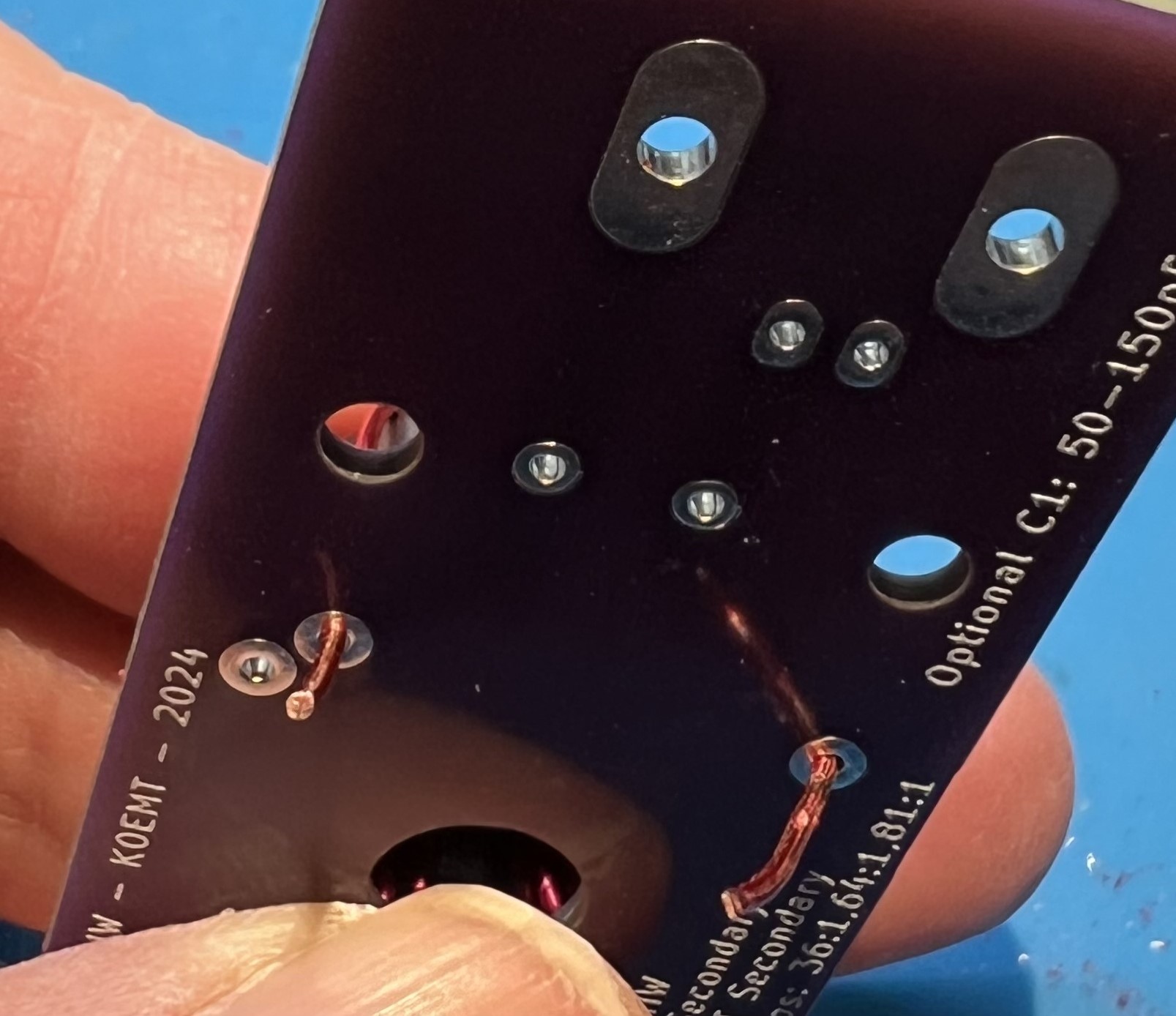
Pictures

Here are a few pictures from the event:

QSL Info

K0C logs show that 77 contacts were made on HF, with two countries.
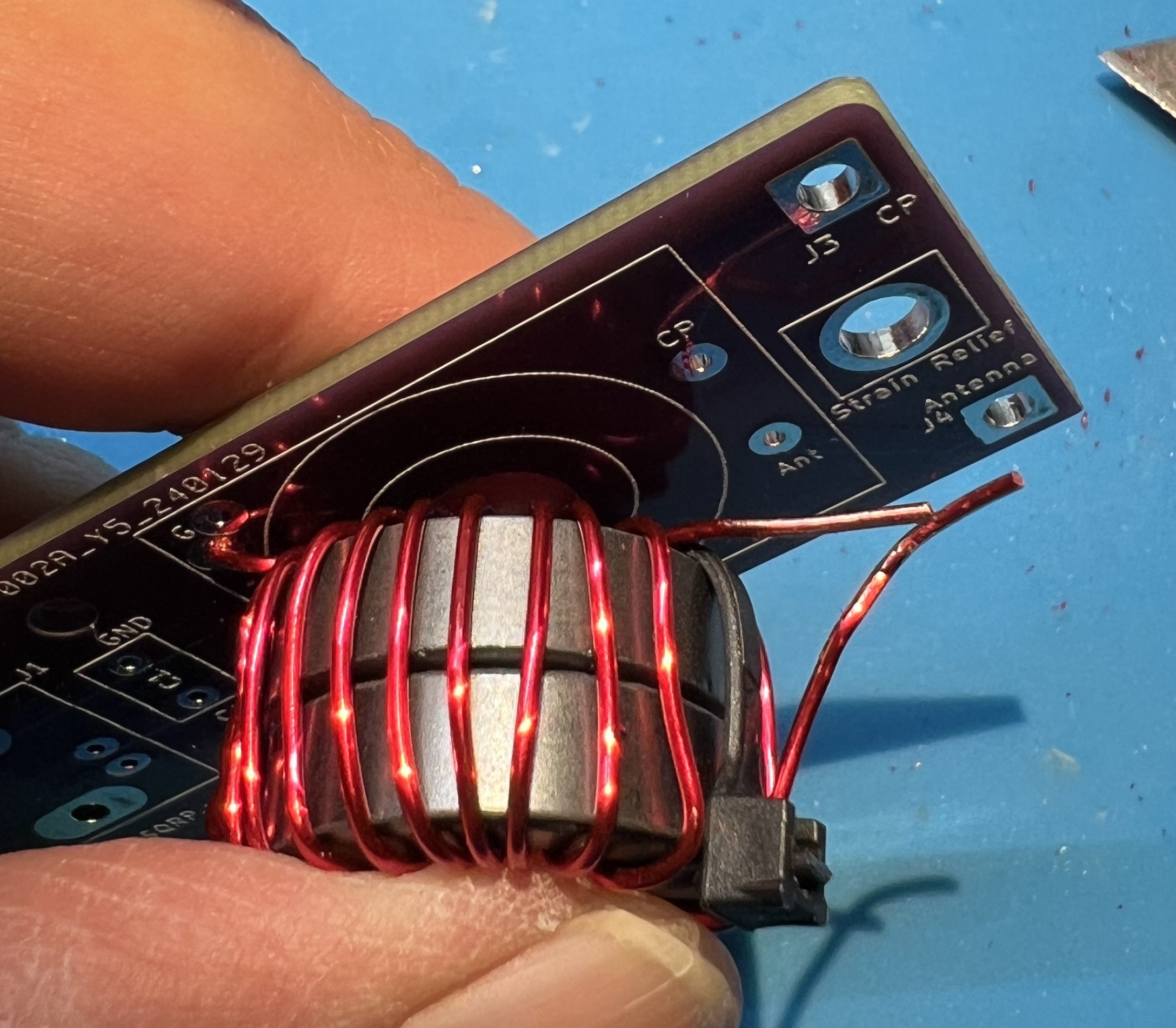
10M 4
20M 70
40M 3

For an event certificate please send your QSL information along with a SASE to NM0X