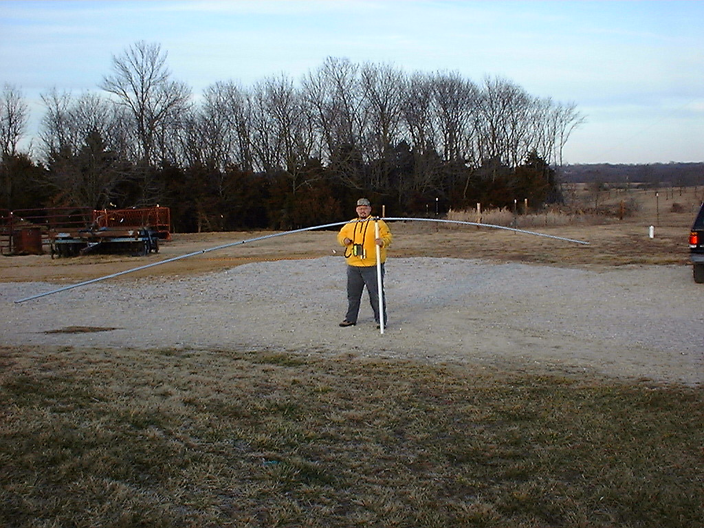
X-Beam Antenna
VHF/UHF X-Beam Construction Notes (and HF see update below) – k0emt
I sat down and drew out what I did and thought I’d pass on what I did/found out.
The design is from The 1993 ARRL handbook that was given to me by WD0HBX.
The x-beam was originally intended as an HF mono-band beam.
I used the formulas to build it for 6m. It also happens to work out really well for 2m & 70cm use as well.
The text says that this antenna design will typically have a 6-8dB gain and a forward to back ratio of 20dB.
The handbook also states that this design should perform as well as or better than a similar yagi.
Notes:
(That will make more sense when you look at a picture.)
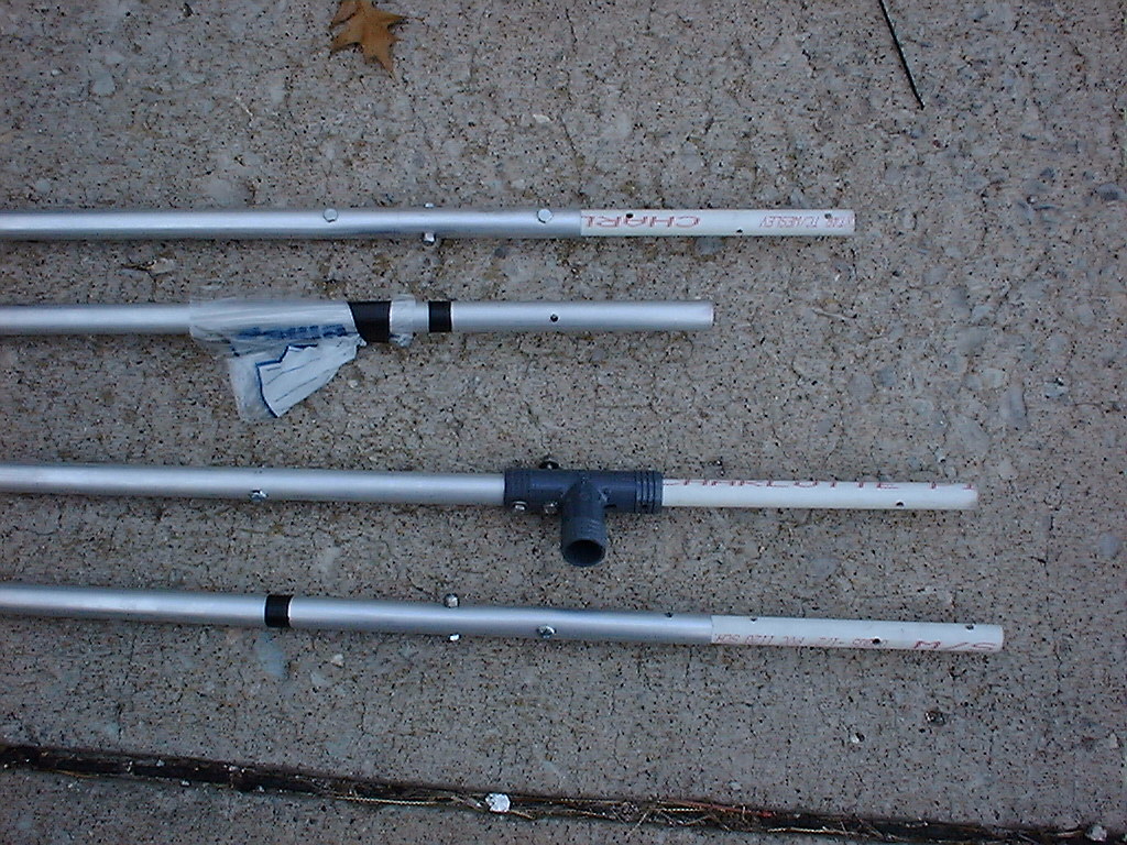
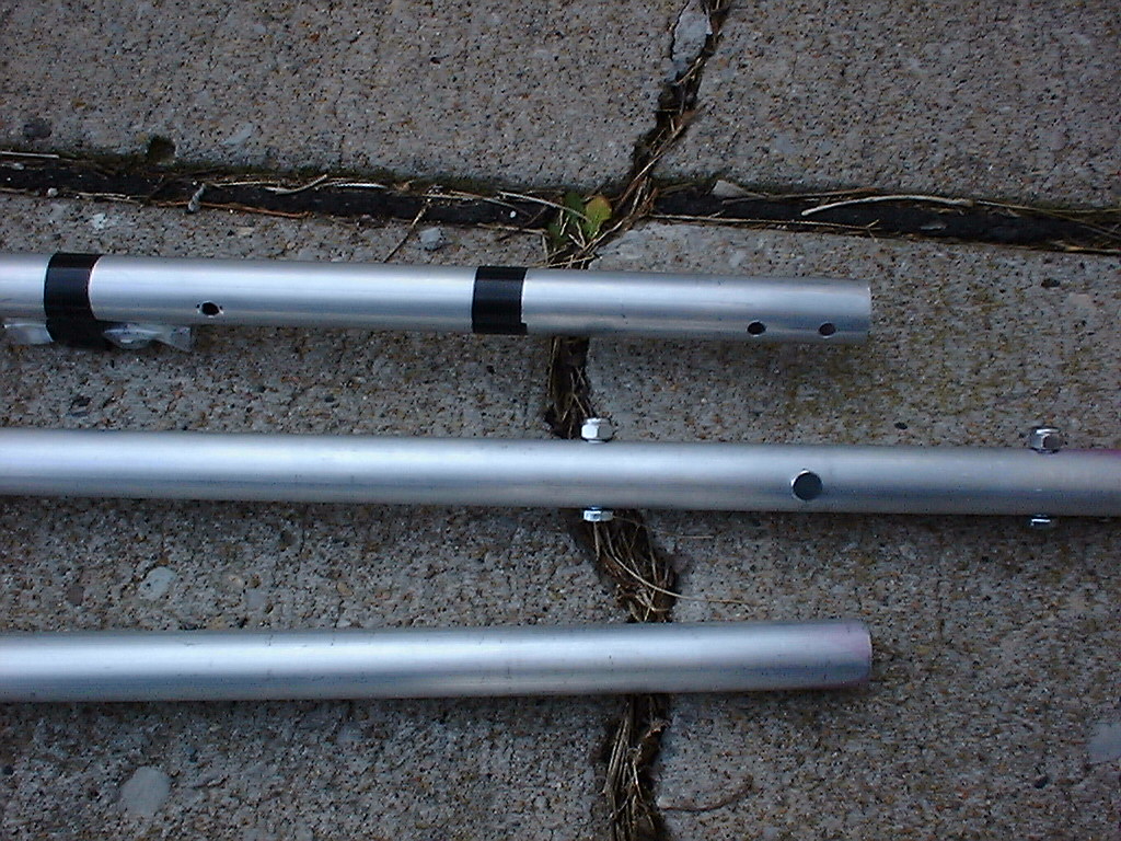
- There are tails on all four arms.
- I didn’t have my arms exactly perpendicular.
- I had the inside angle of the directed element < 90 degrees.
- I used square tubing on the back and round on the front.
- Tie the tails to the nylon cord that is strung around the beam for support.
f       swr
(48.4 - 51.35) <= 2.2
50.110  2.2         420.000 1.3
50.125  2.2         426.000 1.6
52.525  2.5         430.750 1.6
                    435.000 1.1
144.000 1.1         436.300 1.6
145.050 1.2         442.000 2.0
146.000 1.3         444.000 1.6
146.400 1.4         445.000 1.1
146.520 1.4         446.000 1.5
148.000 1.2
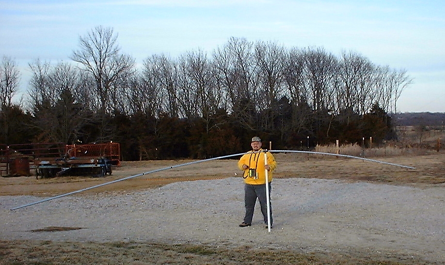
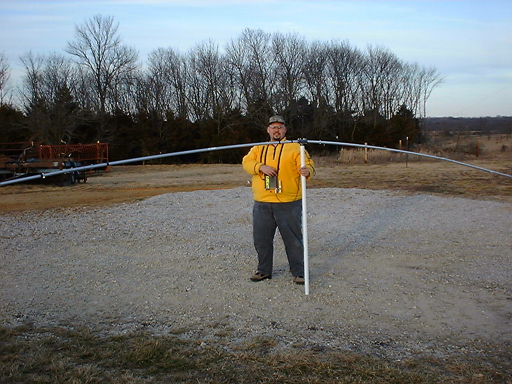
 Figure 1: X-Beam Antenna Design Overview
| Color |
Part |
Description |
| Green |
Directed Tails |
Wire |
| Yellow |
Directed Arms |
Tubing (Wired together at vertex) |
| Cyan |
Project box |
SO-239 (Wires lead from here to driven elements) |
| Purple |
Driven Arms |
Tubing |
| Red |
Driven Tails |
Wire |
| Blue |
Support Cord |
Nylon Cord Runs around perimeter zip tie wire tails to this support also used to provide stability |
 Figure 2: Marked X-Beam Antenna Design
On air testing has shown that it is indeed directional.
Had S-8 noise on discone, switched to beam, now S-3.
Conversely, when testing on 6M with a horizontally polarized “local” station KB0QHZ, noted an improvement of 5 S-units when using beam.
(cross polarization could come in to play though – the discone is vertical.)
When testing with KB0HNR mobile in Jefferson City, MO I was able to copy him at times S5-9 when the discone couldn’t even hear him.
A similar gain was noted when hearing DX when cross-polarization shouldn’t be an issue.
Noted, that when I changed the direction it is pointed wasn’t able to bring up certain local 2M FM repeaters.
Hooked up an ICOM 706mkII, using 20w on 2M SSB made a contact with K9IMX (Lake of the Ozarks), he reported me 57.
He regulary works N9WYX, another “serious” 2M ssb station within ~1/2 mile of my QTH and he said he was impressed with my signal.
As a side effect, it seems like the discone is peforming better now than before.
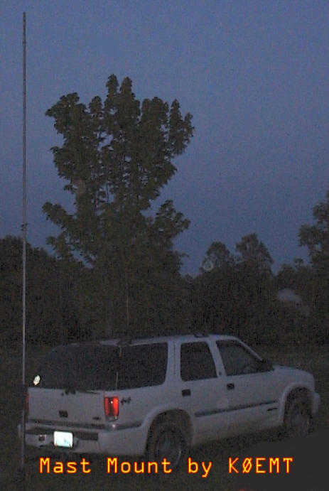
The discone is mounted off the top of a 20’ mast.
The beam is approximately one foot under it.
Maybe, it’s benefitting from some sort of ground plane effect?
Overall, I’m fairly happy with this beam.
I have the feeling I will be building another one this year.
I’ll use better materials and be more exacting on the next go around.
If anyone decides to build one, please let me know.
I’d be glad to help any way that I can and to stick it on the analyzer when you’ve finished construction.
2001 Jan 23
KB0HNR was over recently.
We had the antenna hooked up to my Kenwood TS-570S.
The 570’s tuner matched the rig to the antenna on 20 and 40 meters.
We had a 59 contact into MA on 20m and were able to check into the 3905 net on 40 meters.
Not bad for a VHF/UHF antenna!
2001 May 31
I now think that the reason the antenna was working on the HF bands was because it was so close to ground that there were some very strange interactions going on.
The antenna was on a ground mounted 5ft Rohn tripod, with a 5ft Radio Shack Mast, Rotor & 4ft PVC mast attaching to the antenna.
2M and 440 were exhibiting good SWR but I was having a heck of a time with 6M.
6M would however tune.
Presently, I have moved the antenna a top a ~25ft Rohn 25G tower.
As currently configured I have a 1.1swr for 144.2 and a 1.8swr for 432.1.
50.125 is currently showing a swr of 8.3, Rs=8 and Xs=17.
Just this last weekend I added a 10’ section to the tower increasing it to 25ft.
I believe before I had done this that my swr was < 2.0 on 6M and on 2M,440 it was >1.5 but <3.0.
I am coming to the conclusion that this antenna is very sensitive to it’s height above ground.
For now, I plan to leave it as is, (I don’t climb), and use the internal tuner of the TS-570S to make up the difference.
Which it does just fine.
By summers end I hope to add another two sections to the tower and a hazer.
At that point in time I will try to adjust the antenna or make a matching circuit.
As an aside, the 570 will now tune the beam for 10M.
2001 October 09
Beam is now at ~50ft. It is performing well.
Frequency and corresponding SWR as measured with MFJ antenna analyzer.
| Freq |
SWR |
| 21.450 |
2.6 |
| 21.3– |
2.8 |
| 21.0– |
3.3 |
|
|
| 18.168 |
2.7 |
| 18.068 |
2.6 |
|
|
| 14.350 |
1.8 |
| 14.225 |
1.9 |
| 14.150 |
1.9 |
| 14.025 |
1.8 |
|
|
| 10.15- |
1.5 |
| 10.1– |
1.7 |
|
|
| 7.3– |
5.5 |
| 7.225 |
6.2 |
| 7.150 |
6.8 |
| 7.0– |
8.2 |
|
|
| 4.0– |
8.4 |
| 3.85- |
9.5 |
| 3.75- |
10.5 |
| 3.5– |
25.5 |
| Freq |
SWR |
| 446.0– |
2.0 |
| 432.1– |
1.4 |
| 148.0– |
2.5 |
| 147.0– |
2.0 |
| 146.0– |
1.6 |
| 145.0– |
1.5 |
| 144.2– |
1.3 |
|
|
| 54.0– |
1.4 |
| 53.0– |
1.6 |
| 52.525 |
2.2 |
| 51.0– |
3.2 |
| 50.125 |
3.4 |
|
|
| 29.6– |
3.7 |
| 28.885 |
4.6 |
| 28.5– |
6.0 |
| 28.3– |
6.6 |
| 28.0– |
7.5 |
|
|
| 24.99- |
4.3 |
| 24.93- |
4.1 |
| 24.89- |
3.9 |
I could not get my Kenwood TS-570SG to force feed the X-Beam on 28.337.
It did match it on 29.6.
The rig will also not make the match on 40 Meters.
Obviously it won’t make the match on 80 or 160 either.
2003 April 03
It is VERY important that the arms be of a significantly larger diameter than the tails. More info on specifics can be found at LB’s (W4RNL) page below.
Here are some additional web resources for your perusal.
2025 March
Figure 2 above illustrates the marked X-Beam Antenna Design.
The front yellow and green are a directed element, while the rear pink and red are the driven element.
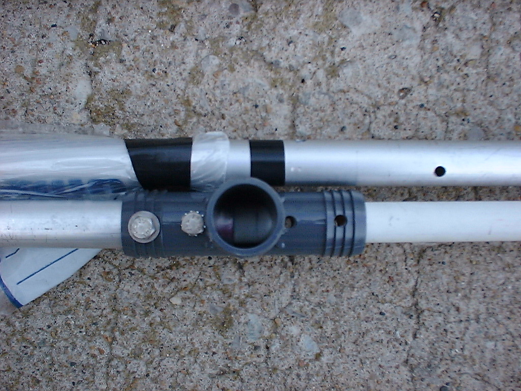
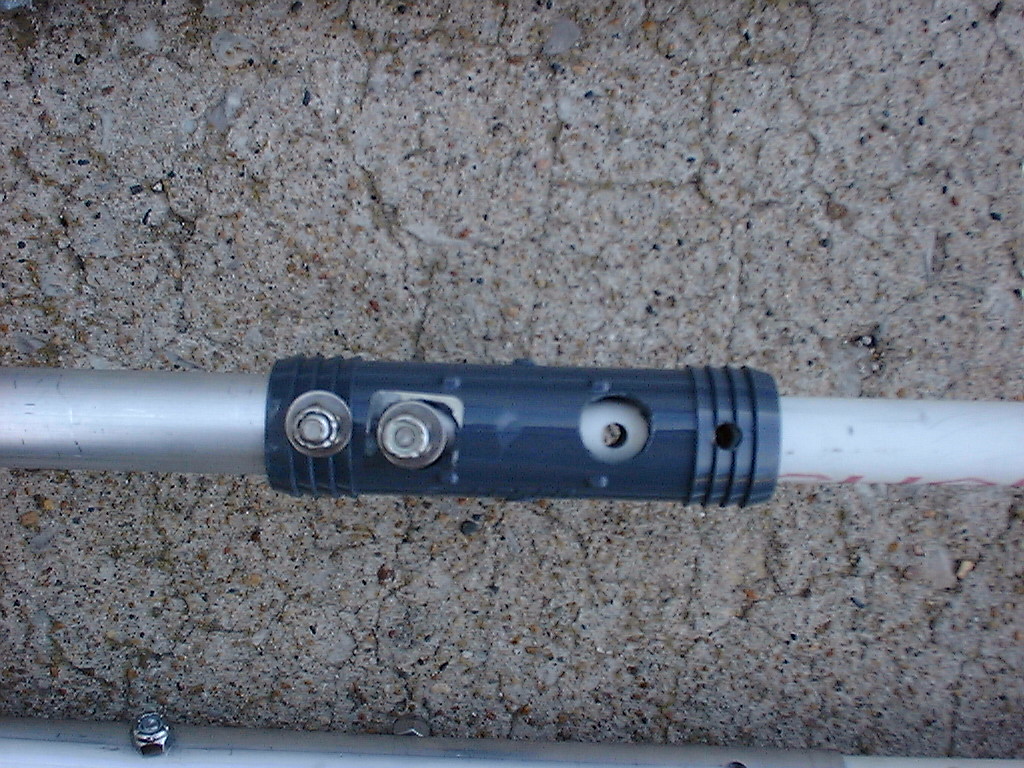
The thin wire does not pass through the larger tubes.
For the directed element (passive), the two pieces of tubing are connected together with a wire jumper.
The green wire tails are connected to yellow tubes at the end using machine bolts/hardware or rivets.
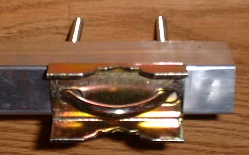
For the driven element (active), the feed box with SO-239 has the shield connected to the end of one tube (pink) and the center pin to the other tube (pink).
The wire tails (red) are bolted or riveted to the tubes.
A 16AWG wire was used for this connection.

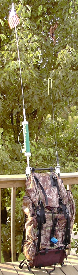
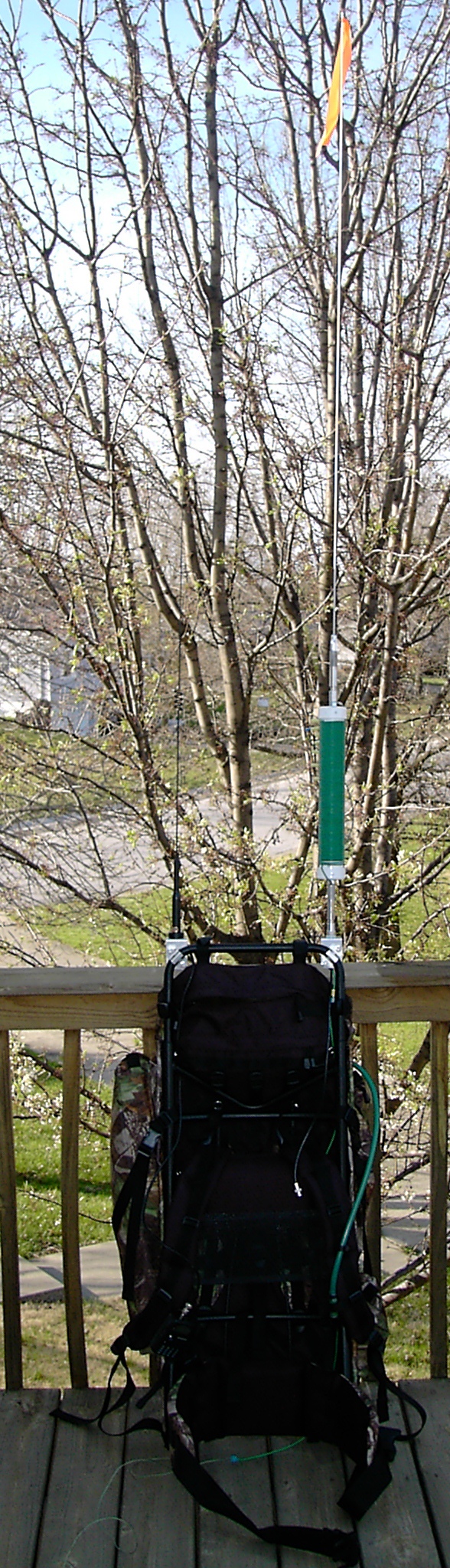
Pedestrian mobile HF/VHF backpack
Counterpoise Length
How long is the counterpoise? The overall length including the "pigtail"
that is attached to the antenna bracket is the appropriate length for the
frequency based on Bonnie KQ6XA's research. Here are some excerpts from the
Counterpoise_Radial_Length file provided by the
HFPack group.
Counterpoise wire touching Earth
The problem of predicting or computing the length of a resonant wire gets
more complex when using dragging counterpoises and very low radials or
radial wires laying partly on the ground. Because of proximity to the earth
surface, the wire needs to be shorter. Earth (soil) conductivity affects the
resonance, so different soil types may require different length
counterpoises. Generally, the more conductive the soil, the shorter the
counterpoise.
Pedestrian dragging counterpoise length With broadly tunable whips (such as
MP-1, mobile whips, etc)
I've found empirically that a pedestrian dragging counterpoise wire can be
about 10% to 25% shorter than the standard quarterwave formula predicts, and
the whip will usually tune to a fairly good 50ohm match. Insulated wire with
low ohmic resistance should be used. For best dragging quality, Teflon or
slick PVC-jacketed or oil-resitant multistrand wire is best. For safety
while walking with a dragging counterpoise, some sort of slip-connector or
an alligator clip should be used so that the connection will break apart if
the wire is caught by a rock or vegetation.
KQ6XA's dragging counterpoise length by band
  |BAND| FEET |
  |----|------|
  |10m | 7.4ft|
  |12m | 8.0ft|
  |15m | 9.9ft|
  |17m |11.0ft|
  |20m |14.0ft|
  |30m |18.5ft|
  |40m |26.3ft|
  |60m |34.3ft|
  |75m |45.4ft|
  |80m |49.3ft|
Pictures
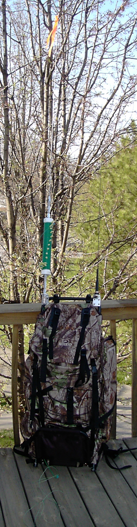
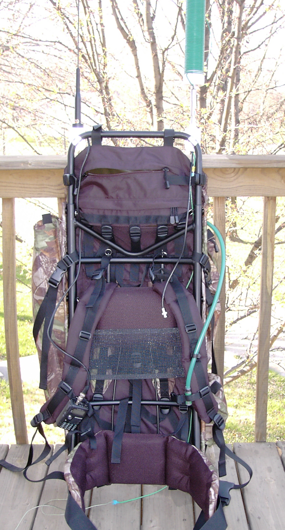
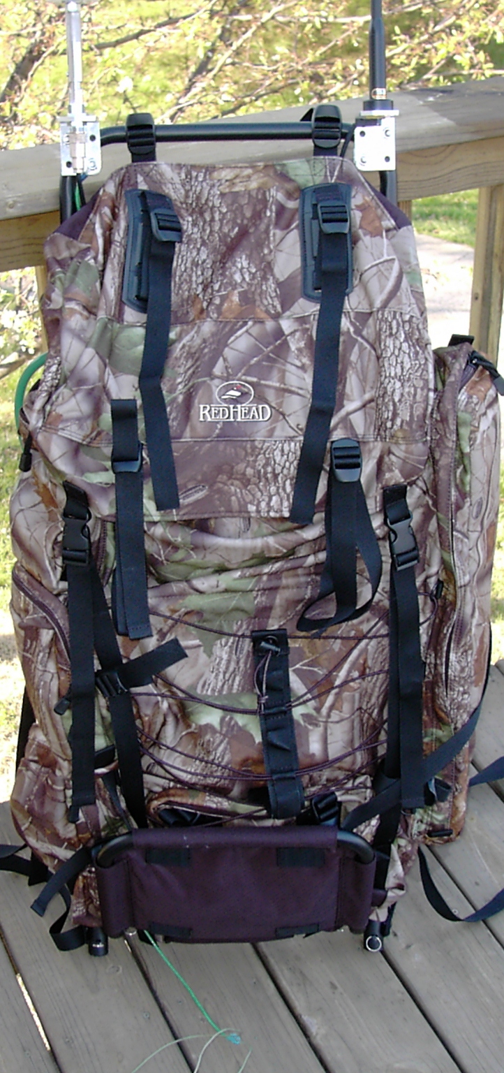
Backpack
I am using a bass pro
big country pack. I picked this backpack for it's external frame, hydration pack and
because it fit me! The frame and padding are set up really nice. They do a
really good job of letting air circulate around. I was really surprised when
I felt a breeze come across my back while wearing it.
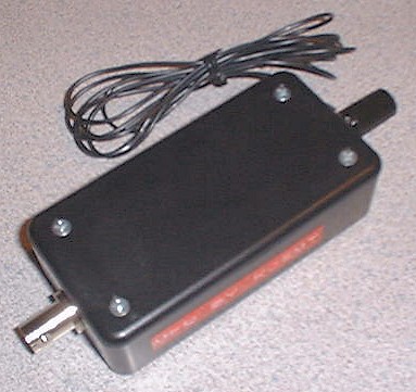
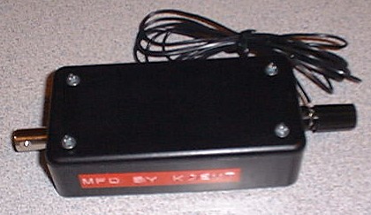
Antenna Mounts
I found some great brackets at a truck stop for mounting antennas. They are
Barjan 300-306, "GM Models" prior to 1990 Mirror Mount. I did grind down the
part of the bracket near to the pack.
One mount is configured with NMO so I have a lot of versatility with it.
Using adapters can go to UHF or BNC F. Coax is terminated with BNC.
The other mount is standard 3/8-24 with a quick-detach stud. Connected a
detachable counterpoise wire to one of the nuts on the mount.
VHF/UHF Station
I use a Kenwood TH-F6a mated with a Comet SBB-5 dual band antenna. The rig
was an easy choice. The main factors were simultaneous dual VFO's, all-MODE
recieve and excellent battery life. I can keep one VFO on a local repeater
or simplex frequency. The other VFO can be monitoring 18.157.5 USB. So, then
I don't drain the HF rig's battery in RX.
The antenna was a tough choice. In the end I went with a Comet SBB-5 because
I like the black color with the pack, the height is just right, flexibility
is good and I had one on hand. Why do I care about height for this antenna?
As you wear the pack it is on the right side. I did this because typically a
brush/trees that hang over the trail are lower on the outside. I'm going to
see how this works out, but I will be very tempted to get one of the new
Comet EX-510B NMO 6/2/440 antennas. It doesn't take much additional antenna
on the F6a to really bring up the receive on HF.
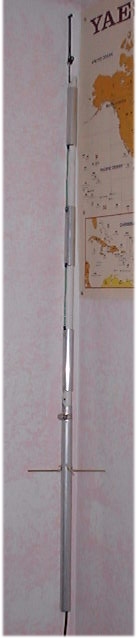
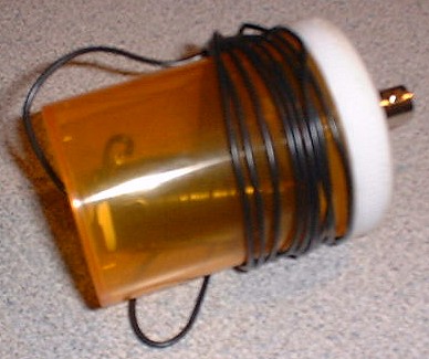
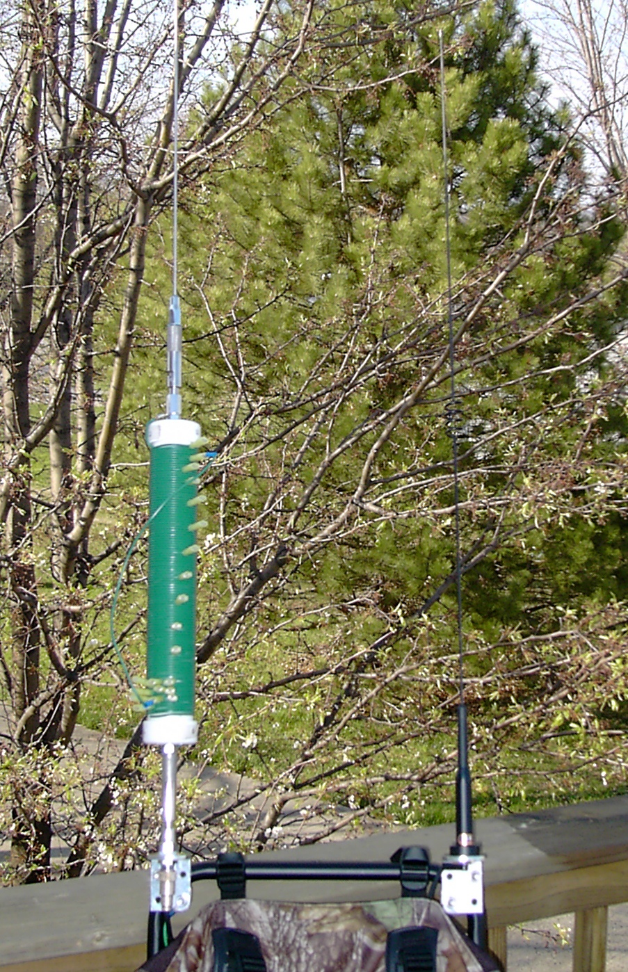
HF Station
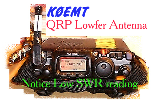
The Yaesu FT-817 is the rig that I use on the HF/50 side of the house.
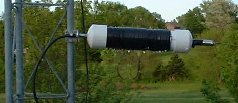
I use the homebrew vertical for the antenna.
- Use the whip only for 6/2M operation ~55 inches.
- Whip w/coil for 10m, 12m, 15m, 17m, 20m, 30m & 40M.
- With the 9ft whip, 80M
-
With the 6 Meter whip and all of the coil bypassed the antenna is resonate
in 10M band.
- With all coil in good to 4.2Mhz.
- With 9ft whip, good below 80M.
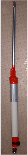
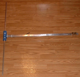
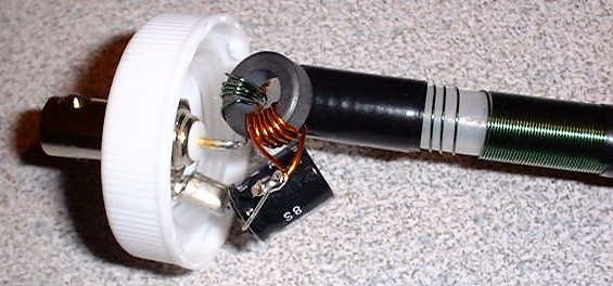
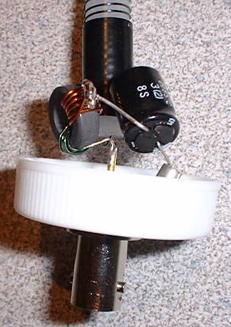
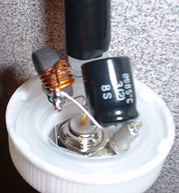
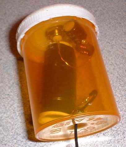
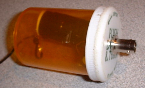
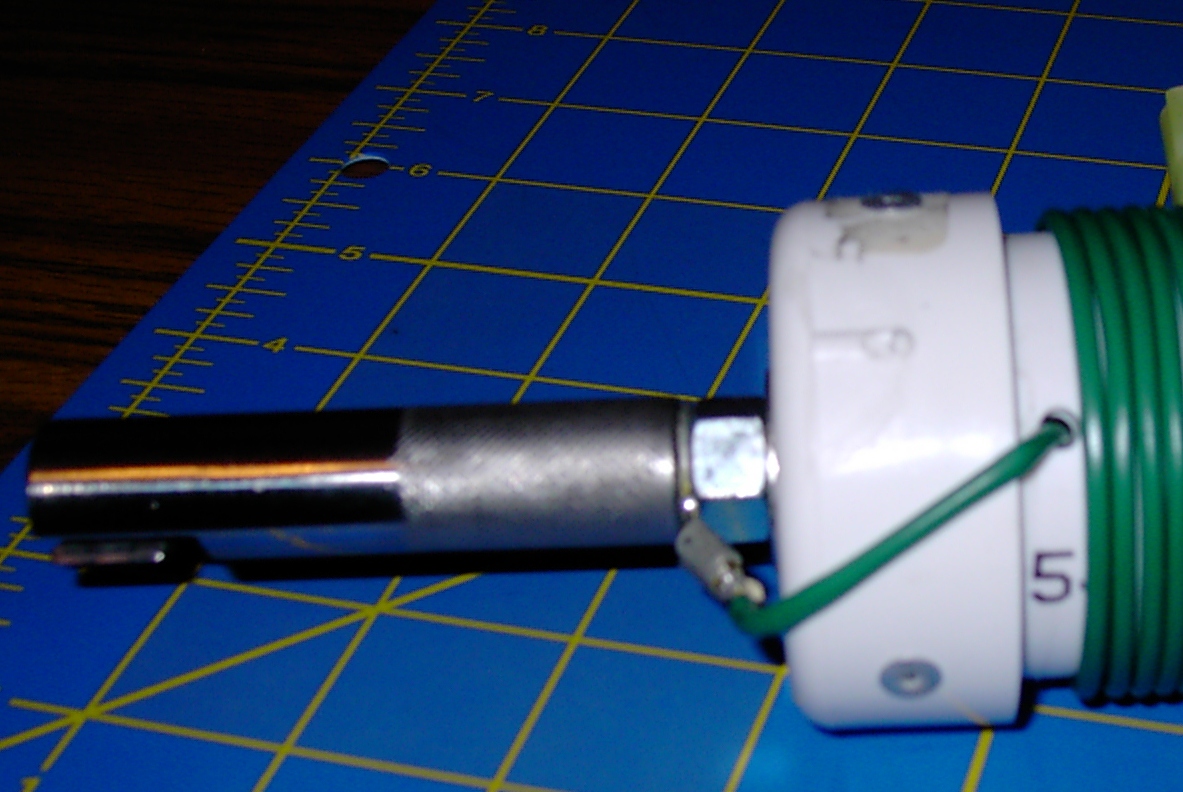
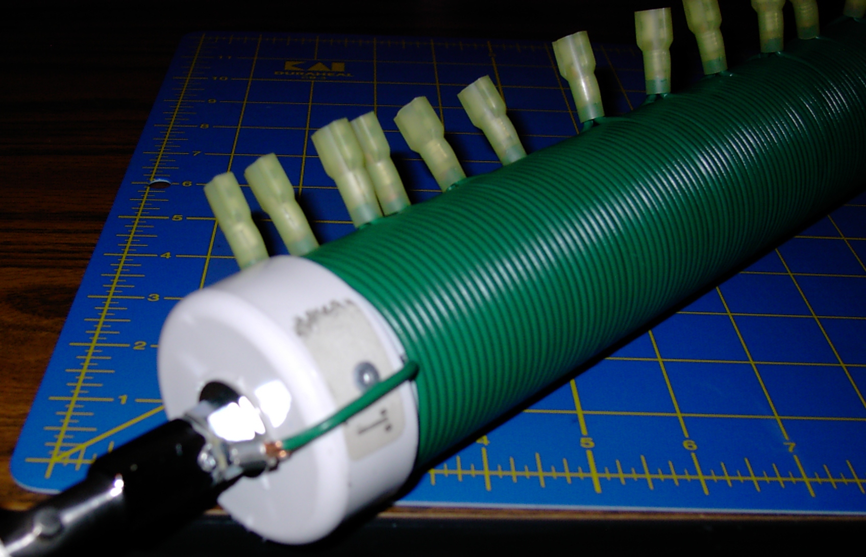
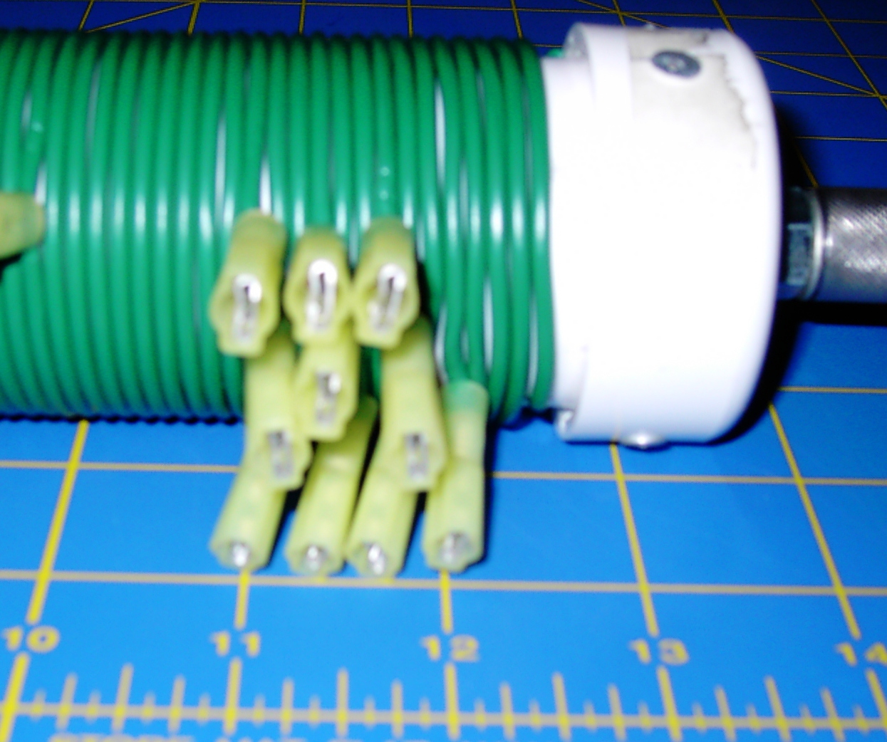
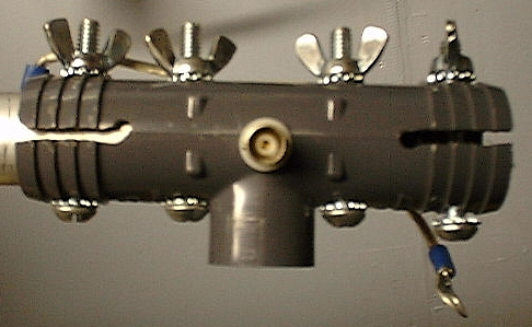
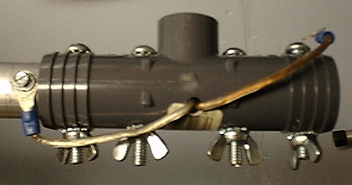
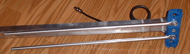
Antenna Construction
-
I used 1 1/2" PVC for the coil form. Female Spade QD's for the taps.
- 16 gauge wire
- didn't calculate taps, evenly spaced at 10 turns.
-
Bottom of coil has 10 turns that are tapped at every turn, use this as
"fine tuning" section.
- Below fine tuning section is 3 turns.
-
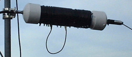
The coil itself is right at 12". This means that there is a little bit of
empty space after the coil then the caps.
-
Use vertical drill press to make holes for 3/8-24 TPI bolts in the
flat end caps. Use lock washer and washer on inside of
cap.
-
End caps were glued on. Then riveted. PVC is a soft material
so it is not unusual for the rivets to want to pull through.
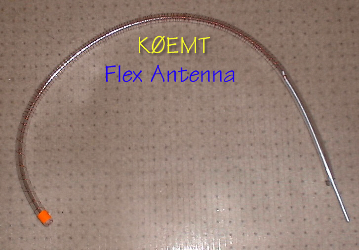
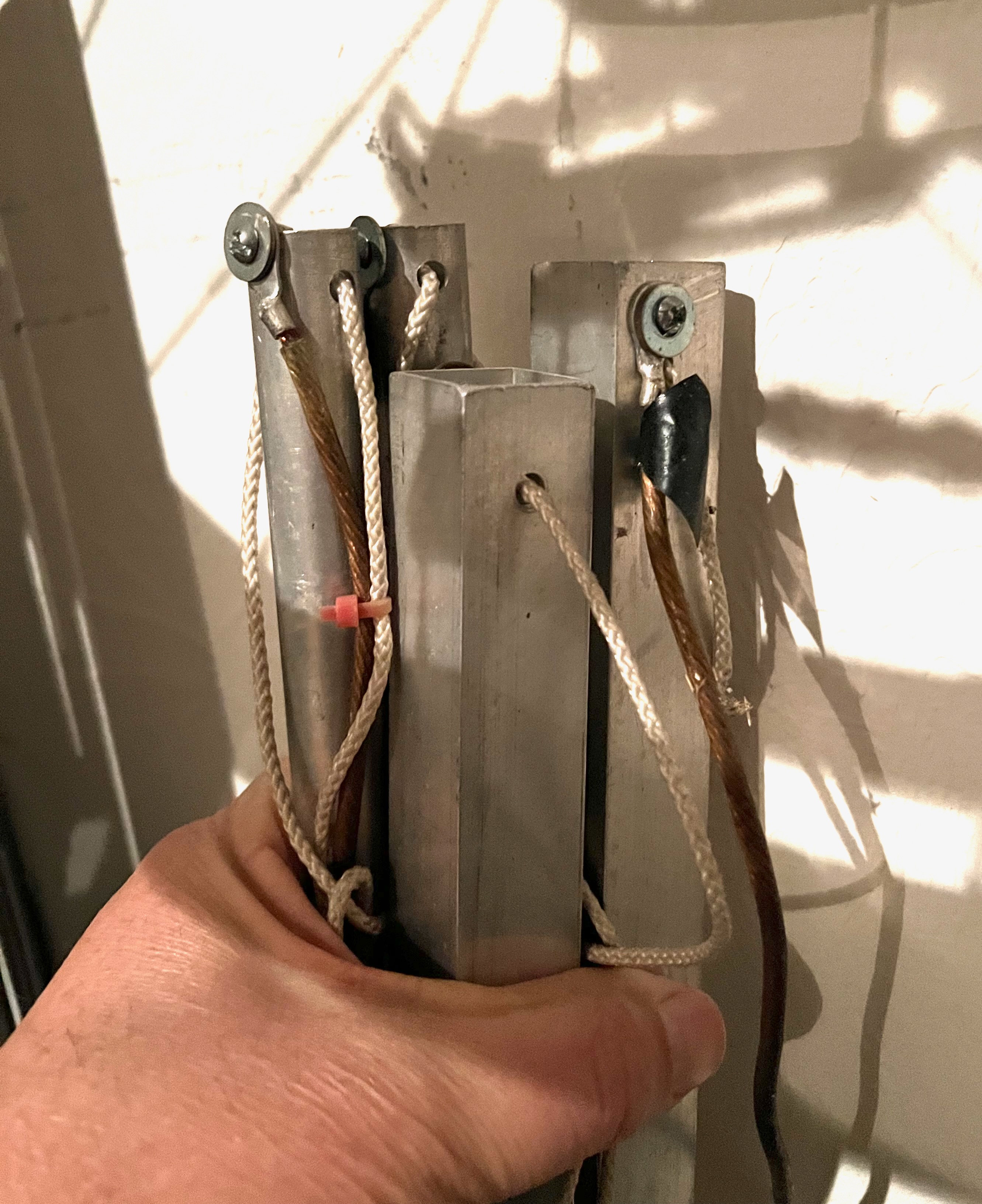
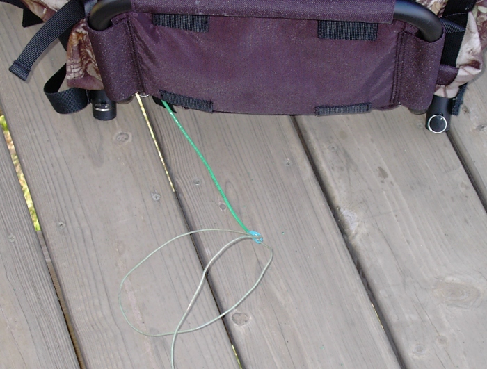
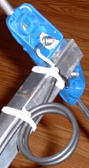
Counterpoise
I have a length of 14 gauge wire that has ring connector on one end and a
female spade connector on the other. The ring connector is attached to the
antenna bracket. The wire is routed down around the outside of the pack to
where it terminates in the female spade connector. I then attach a
counterpoise wire that has a male spade connector on the end. With this
arrangement if the counterpoise gets hung up on something, it disconnects.
Otherwise, the wire could pull on you causing you to lose your balance and
fall. Not a good thing.
Now, the question becomes where to put the quick disconnect? Because of the
way I have my wire routed I opted to put it a couple feet away from the
bracket, past the end of the pack. My thought is to put the quick disconnect
far enough out that you can easily reach back, grab the wire, pull the
connector around in front of you and plug the dragging part back in. Saves
you from having to take the pack off or from practicing to be a
contortionist.
Also, take a piece of flagging tape and tie it to the part of the dragging
counterpoise that is by the quick disconnect. Now when it comes unplugged
you'll be able to quickly spot it. Optionally, use a brightly colored wire.
But be prepared to have LOTS of people tell you, "you're dragging a wire."
Identification and Patriotism
I've also added a yellow ribbon (HFPack identification) to the VHF/UHF
antenna. The yellow ribbon is also a traditional indicator of support for our troops.
Thin, ribbed cloth type, melted the ends to keep from fraying.
On my HF antenna I added a US flag to the top. I used a flag that came on a
round tube. Cut the top off the tube and again below the flag. Secured to
the whip by putting zip-ties in place above and below the flag. HINT: wrap
the zip tie twice and through itself to really snug it up! Now the flag
waves freely when /PM.
Safety
When in an urban environment the ribbon and flag also serve as added visual
attention getters. Especially handy when you're in hilly terrain. I
sometimes find myself out during the twilight hours. For those times I have
an LED flasher on the back of the pack. I also keep an LED flashlight in
one of the pack pockets. Plan your route, follow your route, and make sure
someone knows you're route and expected times. Pretty much your standard
hiking/backpacking safety rules apply.
Be safe and have fun! 73 -- de Bryan, K0EMT


