Kit Information
Kit Builder Resources
Instruction Guides
- 2020 N0SS homage noise generator kit build guide
- 2021 Antenna transformer board guide
- 2024 End Fed Half Wave transformer
- 2024 End Fed Random Wire transformer
- Manual T-Match Tuner
This page will be continually evolving. Primarily, I will be documenting the stuff that I use at my workbench. Although, I may share items that I’ve heard about from my fellow builders. I’ll also include some Next Level sections with gear that more advanced hobbyists or those with more resources may want to consider.
While the tinySA is an attractive option radio amateurs will quickly find that the RBW isn’t narrow enough for their applications.
With these scopes you’ll find higher frequency range, more channels and logic capture.
You’ll find more precision and a greater range of operation with these bench meters
There are a great variety of battery capacity checkers and chargers out there. I like the compact digital battery capacity checker and the HTRC LiPo 2S/3S charger for compact travel gear.
The battery charger I use is a version prior to the one listed above.
I use a Bioenno 12V 12Ah when I want to operate portable with my Yaesu FT-891. The battery is in an enclosure from Portable Zero. Now they are making a nice enclosure that will hold 2 6Ah batteries and mates directly to the FT-891.
A friend recently picked up a nice compact 8Ah.
Typically, I operate QRP portable. That is why I have opted for 3S1P batteries. They provide enough voltage and capacity for the miserly needs of many QRP radios.
Besides using in an external case 8AA case with switch, I use the Eneloop NiMH batteries in my Elecraft KX3.
You can make use of egg cartons, yogurt containers, or tackle boxes for parts organization.
Utilize can “flats” to keep small parts organized and easily accessible while working on a project. You can even stick components with leads into the sides of the flat.
Also, magnet parts trays are great for keeping small parts from getting lost.
20m/40m antenna kit
N6ARA has some nice kits available. He also has a YouTube channel with build videos for his kits and other projects.
K6ARK designs really tiny stuff. He has a YouTube channel with build videos for his kits and other projects.
Amazon has a variety of kits available. Search for “solder practice kit”. I’ve built retro style handheld game and a “Christmas tree” kit. They are fun and a good way to practice soldering.
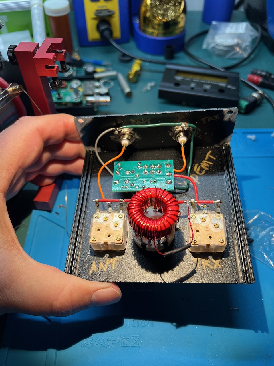
This manual T-match tuner kit came to me via Amazon. It is also available via eBay and other online stores.
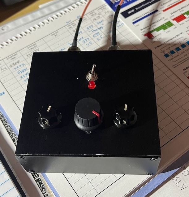
You build this kit into the bottom of the enclosure that is provided. I opted to build it into a 40 x 100 x 110mm aluminum enclosure. Around the machine bolt areas coating was removed to ensure the entire case is bonded together. During assembly, I bolted the main front panel and back panel together.
Don’t trust the sticker guides in the kit. Figuring out how to align them can be tricky with the default case internal structure. Size and locations may not match the hardware. A big gotcha can be the screws that hold on the polyvaricons (printed holes too big).
The board does not have through hole plating.
There is one capacitor that is provided for the N7VE tuning circuit. Make sure to check its value. Mine was out of spec by 50%! I replaced it from parts on hand.
The circuit diagram for the N7VE transformer is correct. However, the board is incorrectly labeled. 2T on primary, 5T on secondary.
Check that the provided enamel coated wire is of the correct size 22 AWG.
The knobs and hardware for the polyvaricons are awful. Plan on doing something different. Again, I pulled from parts on hand for shaft exentions and knobs.
The 4S QRP T-match kit instructions tell you to do taps with the following number of turns: 1,1,1, 2,2,2, 2,2,2, 2,2,2.
Default instructions see the circuit diagram in the marcel wiki page give a sequence of turns starting 10,2,3,2,…
The correct way is to flip the order: 1,2,2,2,4,2,3,3,2,3,2,10
Why? Otherwise, your first turn is 10 turns. This is way too much.
What’s the benefit of this sequence. Fine tuning at the start for when you are using an antenna like a dipole or end fed half wave. Bigger jumps to get you into the 40m band when using an end fed random wire. And a really big jump at the end to help get you to 160m.
Besides removing case coating from where it goes together, I also remove it where the BNCs were installed. There was good continuity between the BNC shield/ground side. However, for clarity I went ahead and connected the ground tabs together.
The switch and inductor:
The 4S QRP instructions tell you to set the polyvaricons to minimum. I didn’t do that.
The procedure:
My antenna is 9:1 unun, ~58’ end fed random wire, with an elevated radial that is ~17’ long to a 20m trap, then another 18'.
With this tuner and my antenna configuration I was able to get matches on all bands 10m-160m.
See the information on multiple ways to tune.
I’m tempted to build one of these again. What would I do differently? I’d probably use the internals from a 4S QRP kit. The 12 position switch is much nicer mechanically to work with. I like the idea of a red LED diminishing as a green LED brightens for tuning. The shaft extensions for the polyvaricons and the accompanying knobs in the 4S kit are much better.
I do like the case and arrangement I used. I would need to construct something to implement the 2 color tune indicator.
Maybe, just build the 4S QRP kit, use the alternate number of turns and case mounted BNCs.
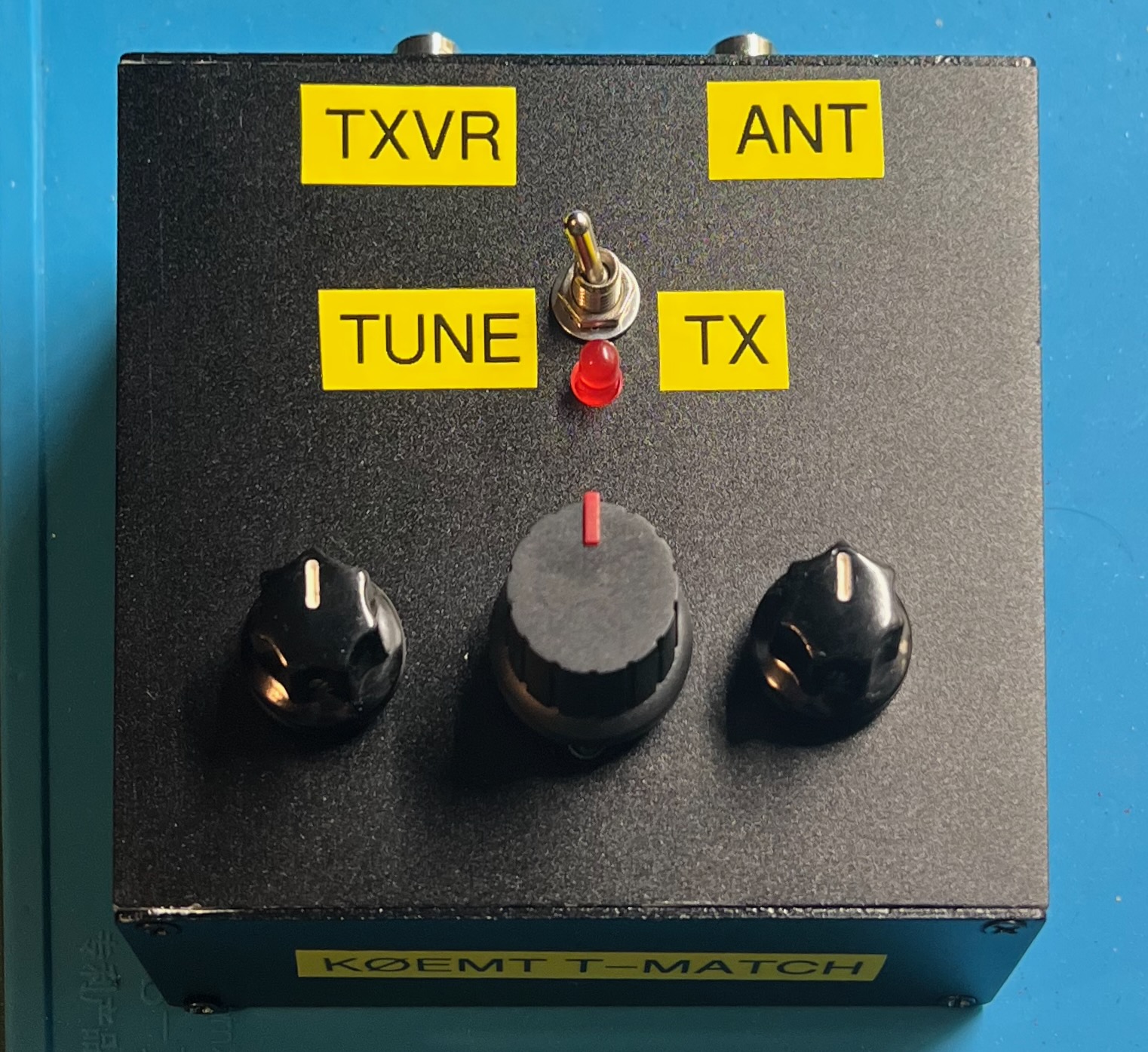
Read about the T-match
There are various ways of tuning the T-match. Some are more lossy than others.
The procedure:
The procedure:
The procedure:
With the min-C and max-C approaches I often found that when it came to fine tuning I was stuck since the other control was either at a minimum or maximum.
The procedure:
Select a frequency, then tune for a match using the various procedures.
| Frequency | Procedure | SWR | Log Mag dB | Notes |
|---|---|---|---|---|
| 28.060 MHz | min-C | 1.115 | -3.42 | |
| 28.060 MHz | 1/4-C | 1.014 | -2.92 | |
| 28.060 MHz | mid-C | 1.034 | -2.82 | |
| 28.060 MHz | max-C | 1.28 | -13.16 | |
| 14.060 MHz | min-C | 1.361 | -1.05 | all inductor – no C added |
| 14.060 MHz | 1/4-C | 1.349 | -1.10 | mostly the same |
| 14.060 MHz | mid-C | 1.041 | -4.13 | |
| 14.060 MHz | max-C | 1.036 | -8.75 | |
| 7.1 MHz | min-C | 1.290 | -1.29 | all inductor – no C added |
| 7.1 MHz | 1/4-C | 1.108 | -1.99 | |
| 7.1 MHz | mid-C | 1.062 | -4.48 | |
| 7.1 MHz | max-C | 1.051 | -13.12 | C2 at max |
| 3.58 MHz | min-C | 1.142 | -3.79 | |
| 3.58 MHz | 1/4-C | 1.089 | -4.42 | |
| 3.58 MHz | mid-C | 1.48 | -5.35 | |
| 3.58 MHz | max-C | 1.393 | -14.9 |
Nice video from @TheSmokinApe on insertion loss. Illustrates using a nanoVNA for tuning.
Getting the Most Out of Your T-Network Antenna Tuner
QST January 1995, pp. 44-47
Here’s how to adjust this popular tuning circuit so it transfers maximum power to your antenna.
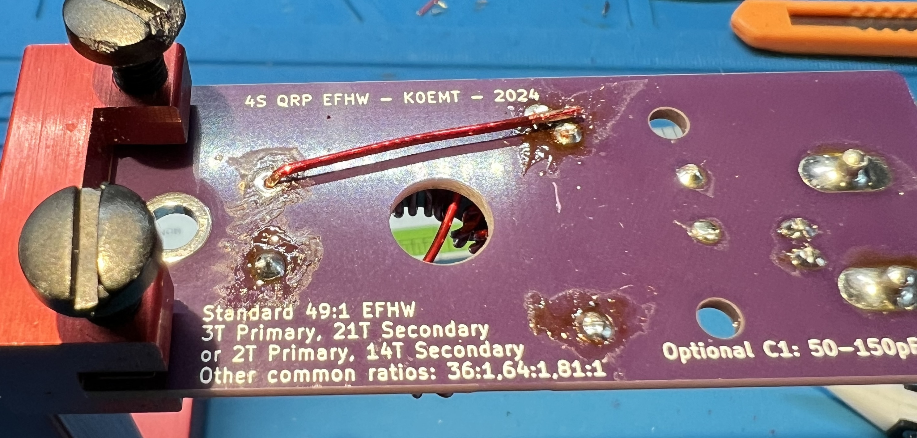
Resist the urge to follow the convention of installing small components first!
By delaying the placement of the capacitor we’ll be able to do some test checks and give ourselves some more room to work.
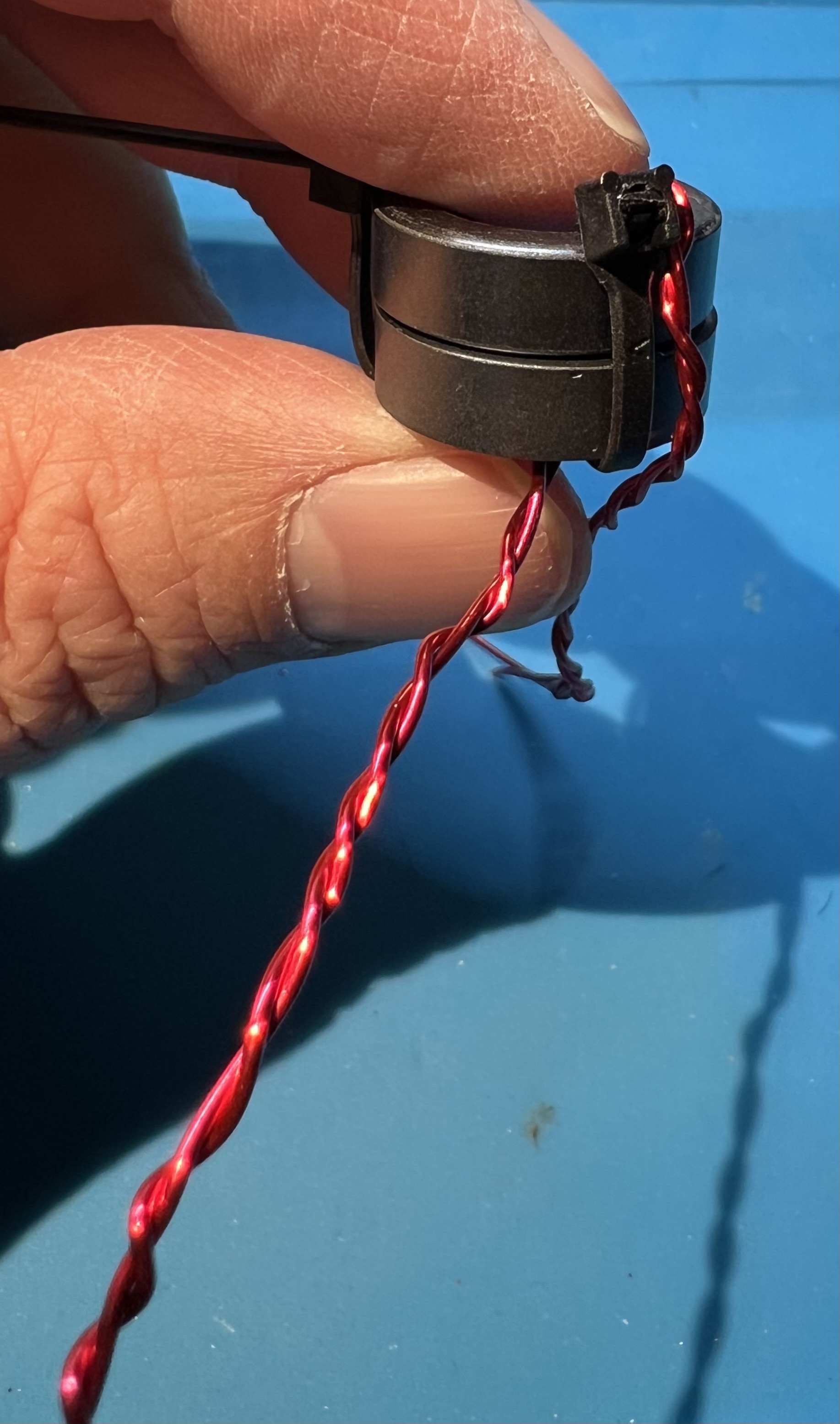
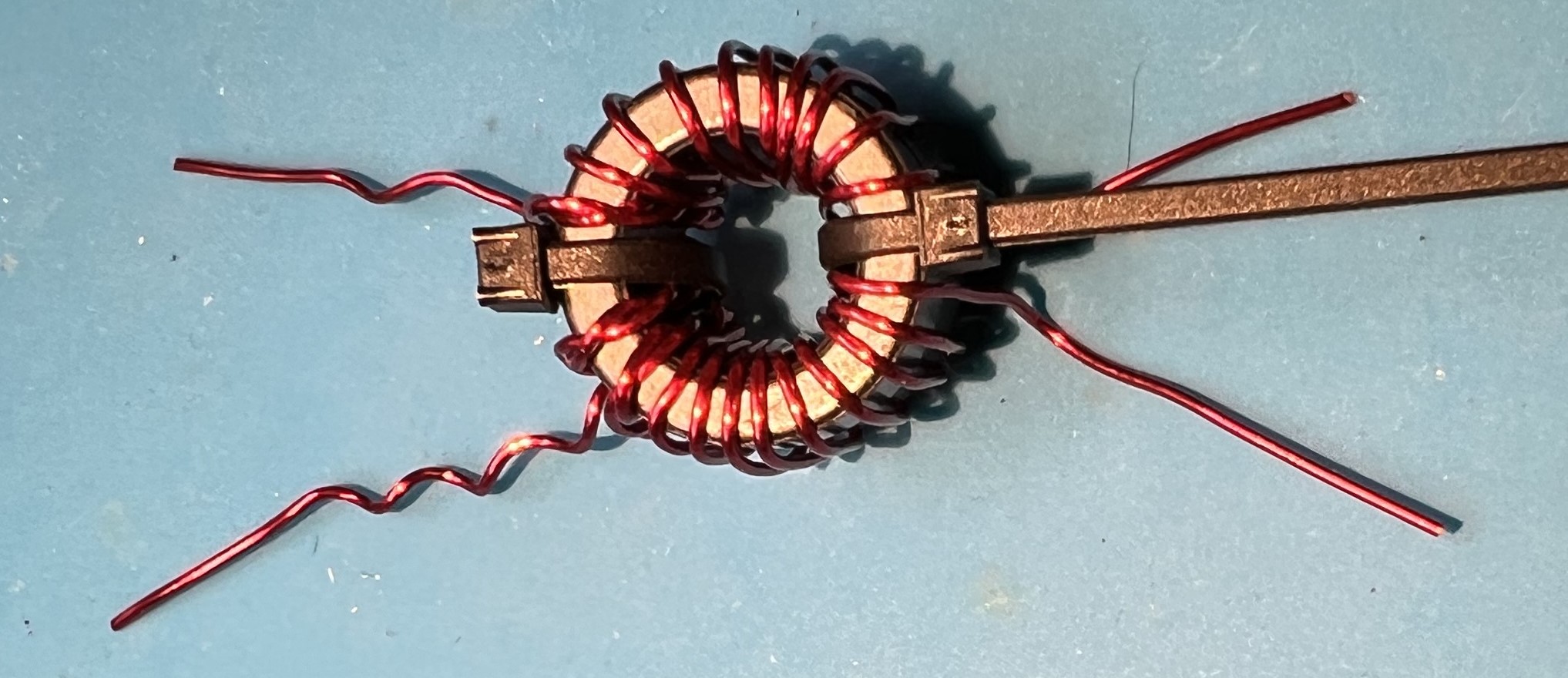
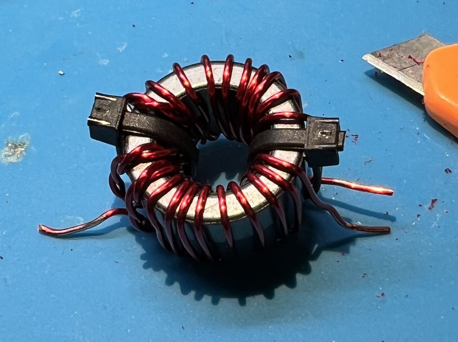
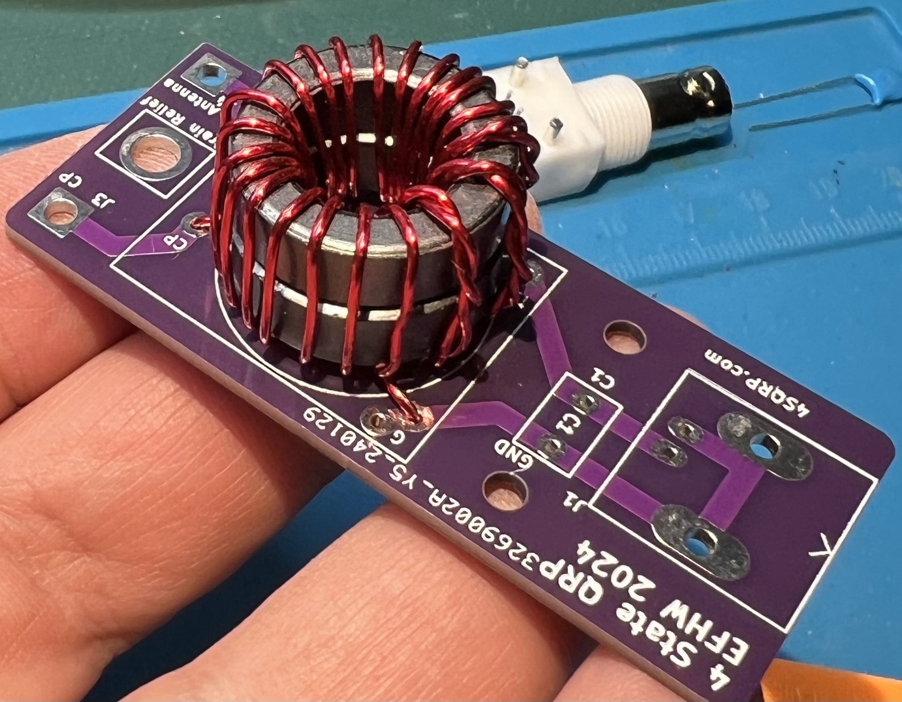
Use 20awg enamel coated wire. Primary uses 8" of wire, secondary uses 35" of wire.
The bare board.
The capacitor, FT82-43 toroids, zip ties, and female BNC.
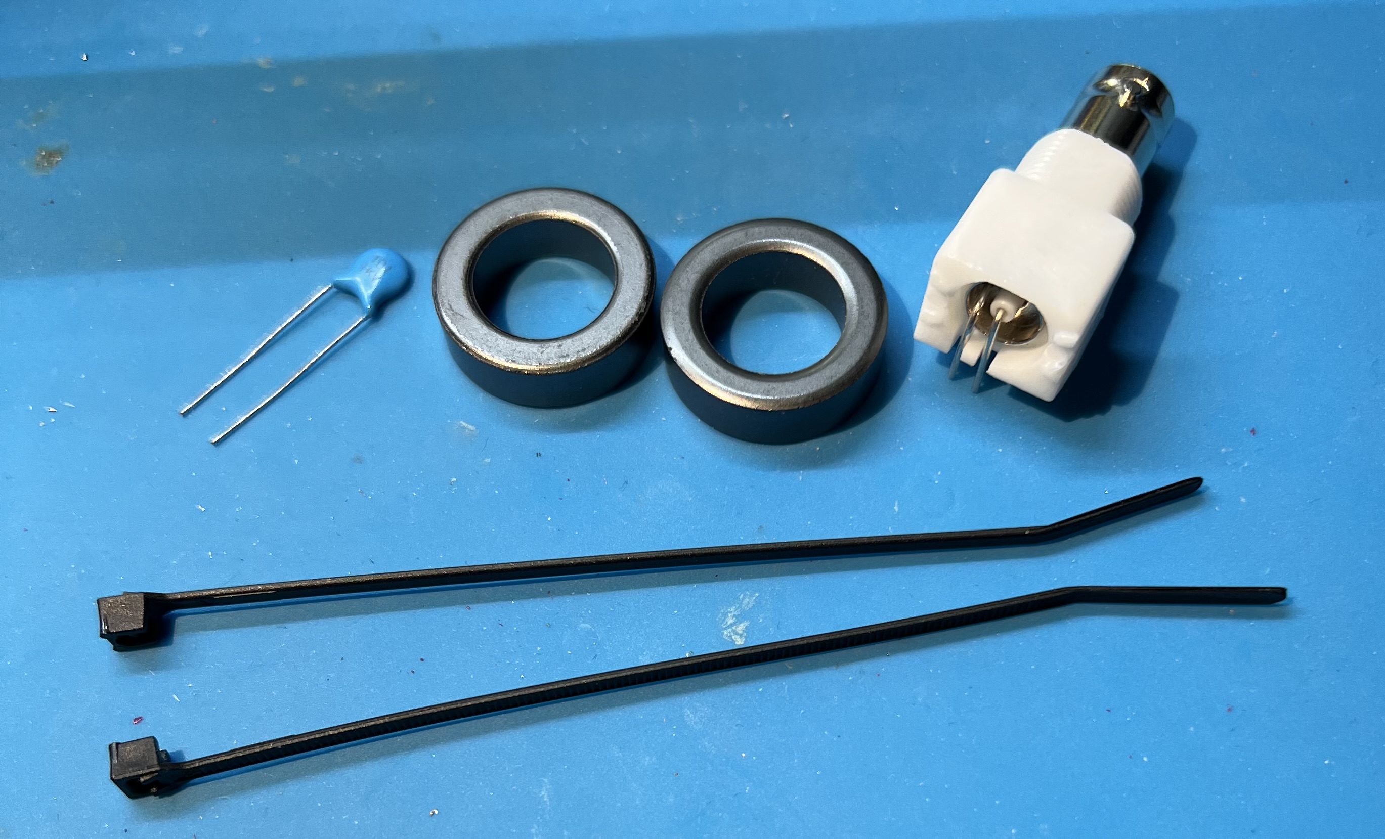
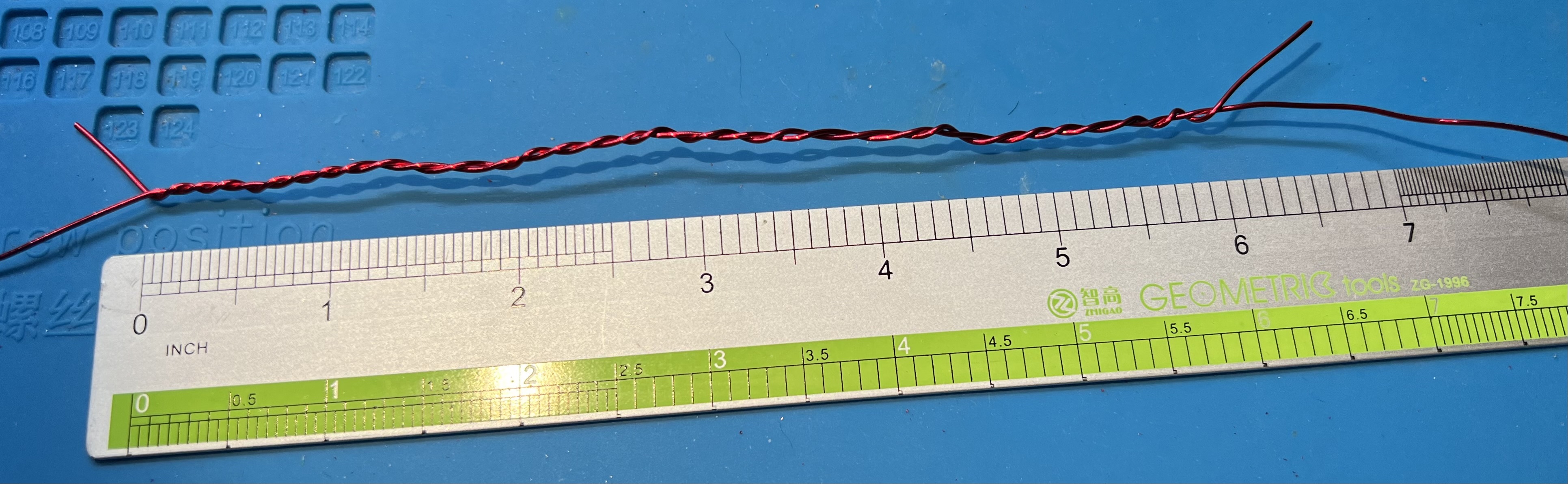
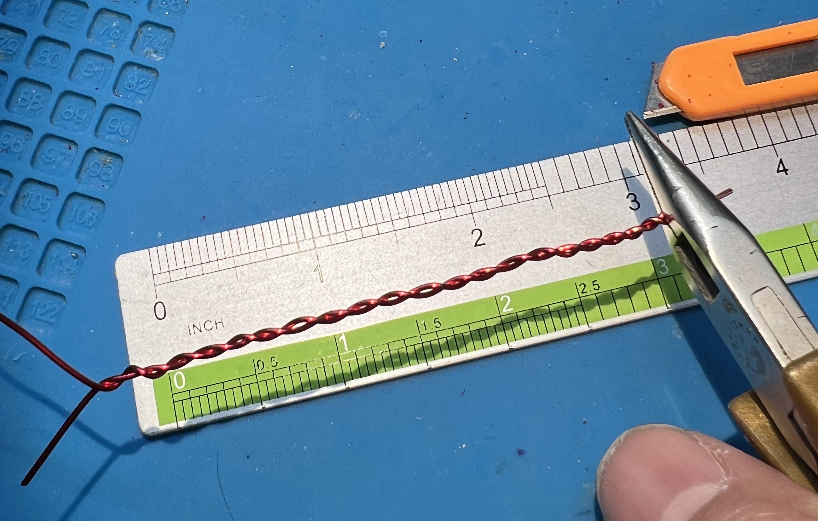
Cut your 8" wire from your length of wire.
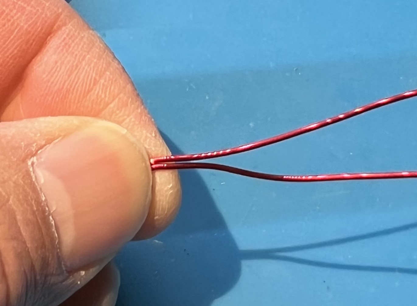
Fold them both in half to find the middle of each wire.
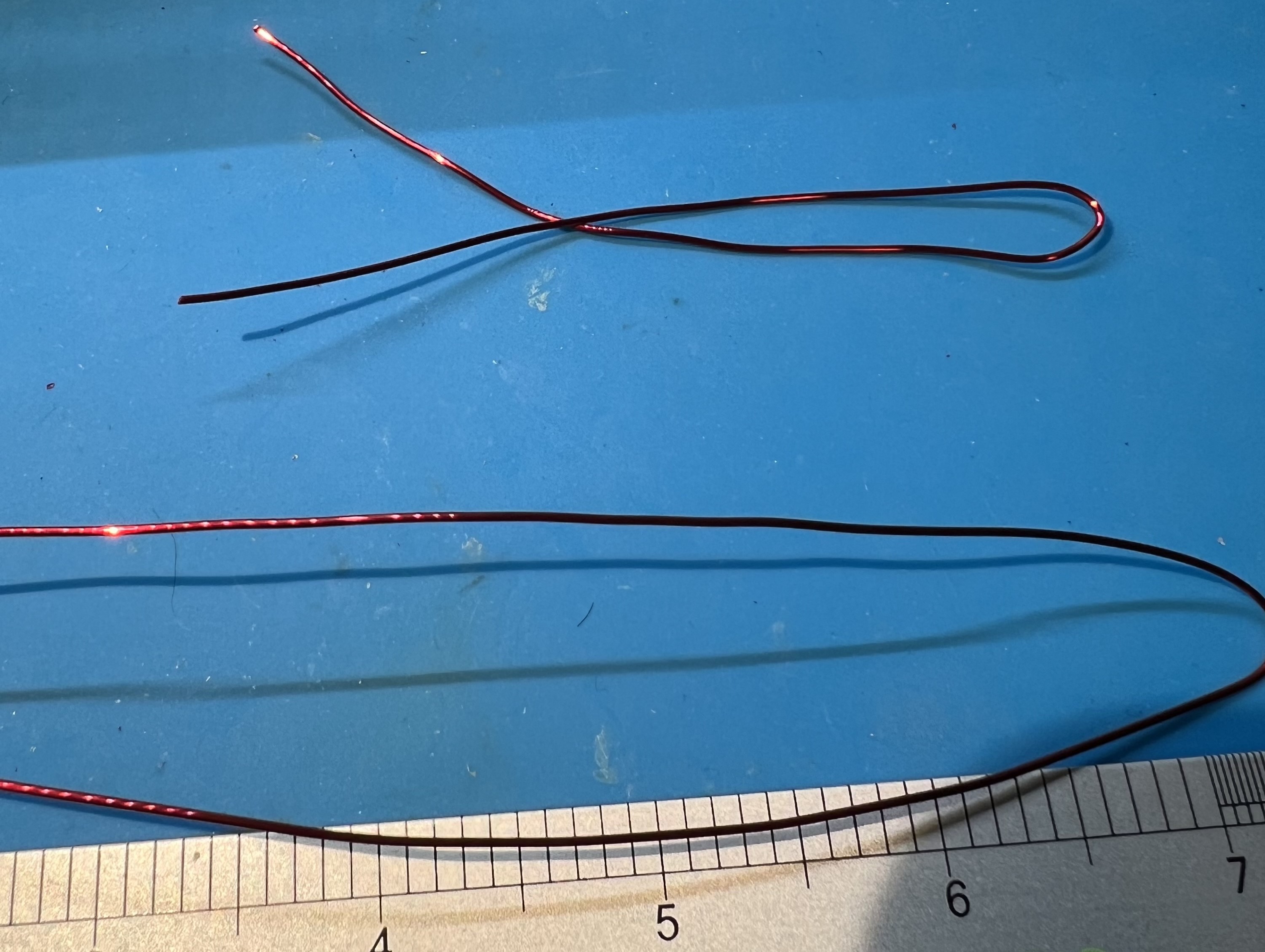
Grip the wire in the middle and twist some in each direction.
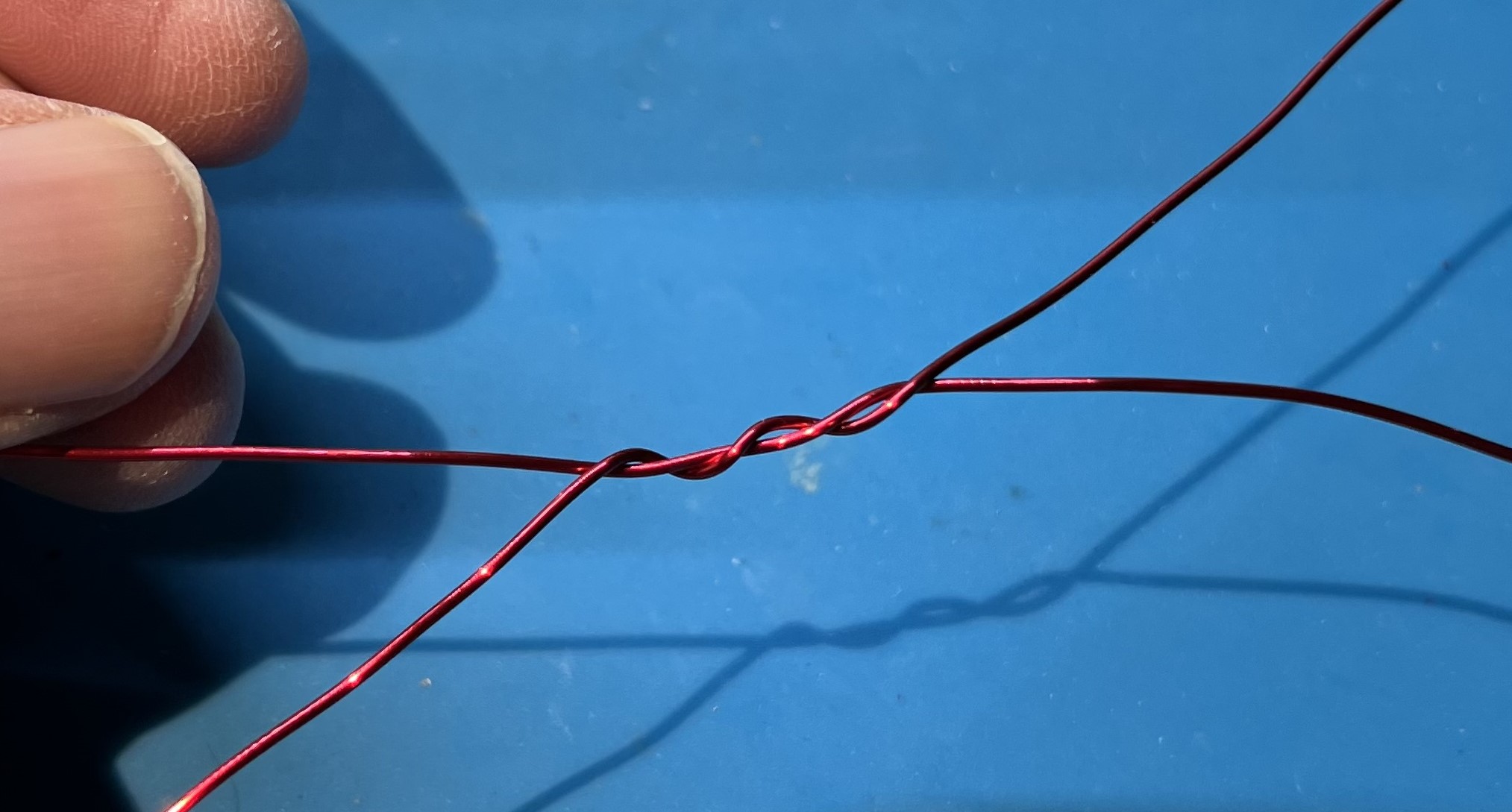
You need about 6" of twisted wire.
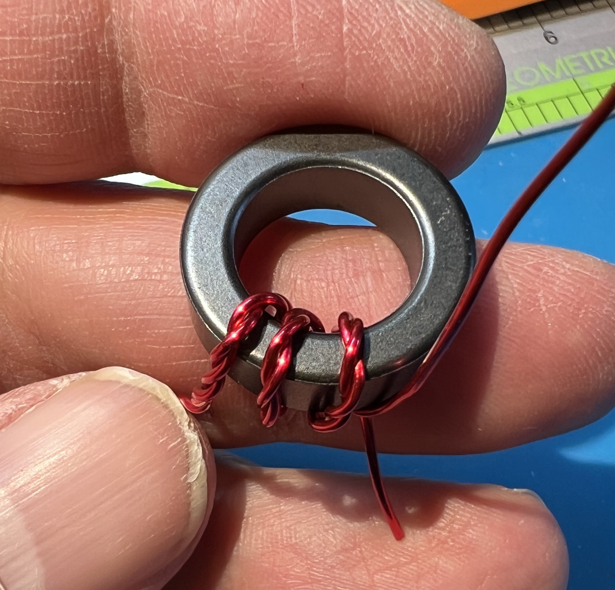
Use one of the zip ties to hold the double stacked toroids together.
Insert an end of the wire through from the top.
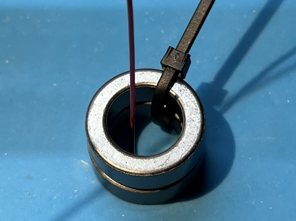
Place the first turn of the twisted wire on the toroid.
This should be in the middle of the twisted section.
Use the second zip tie to secure the first (middle) turn of the twisted wire on the toroid.
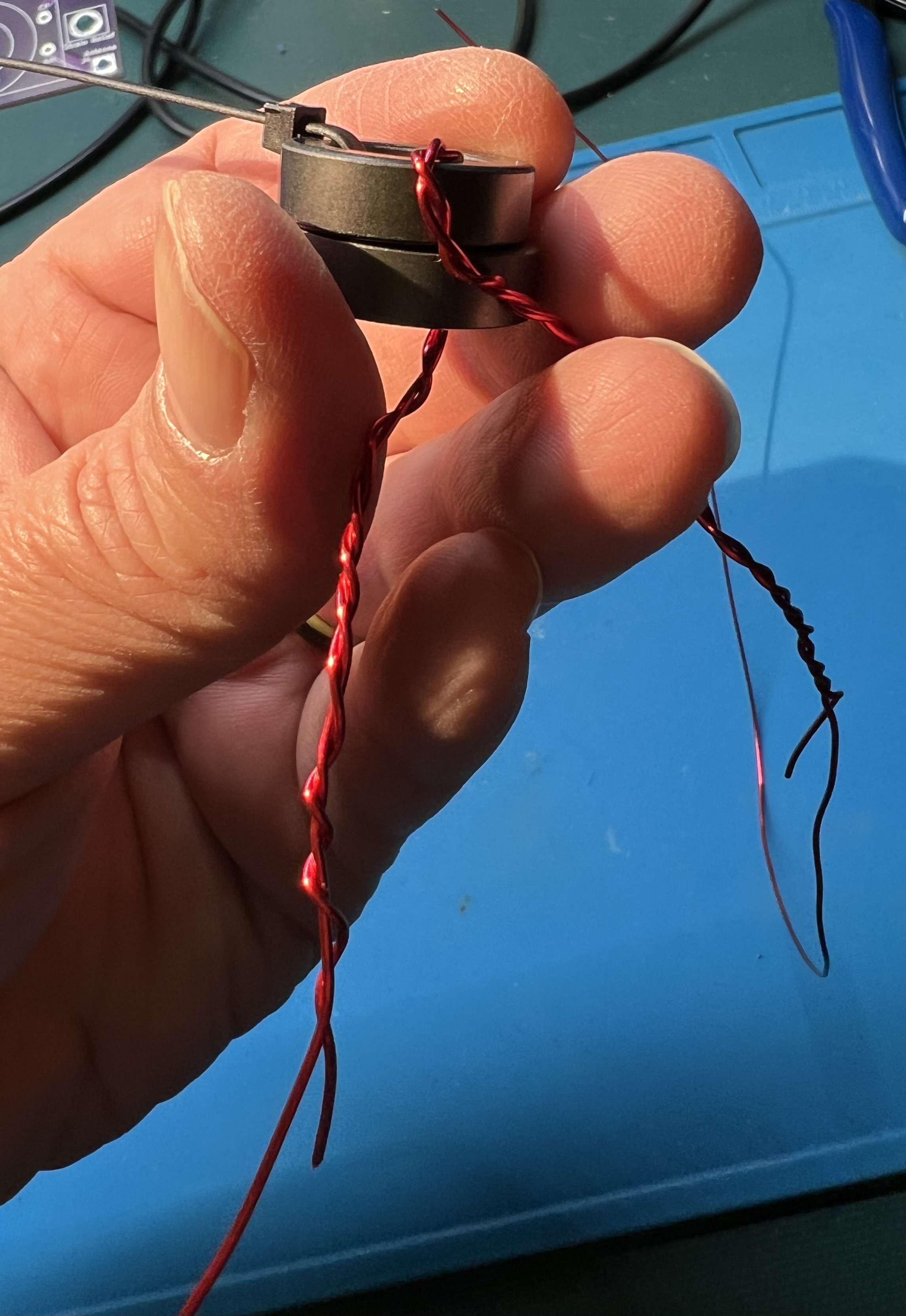
Wrap an additional turn with both wires to the left (clockwise).
Wrap an additional turn with both wires to the right (counter-clockwise).
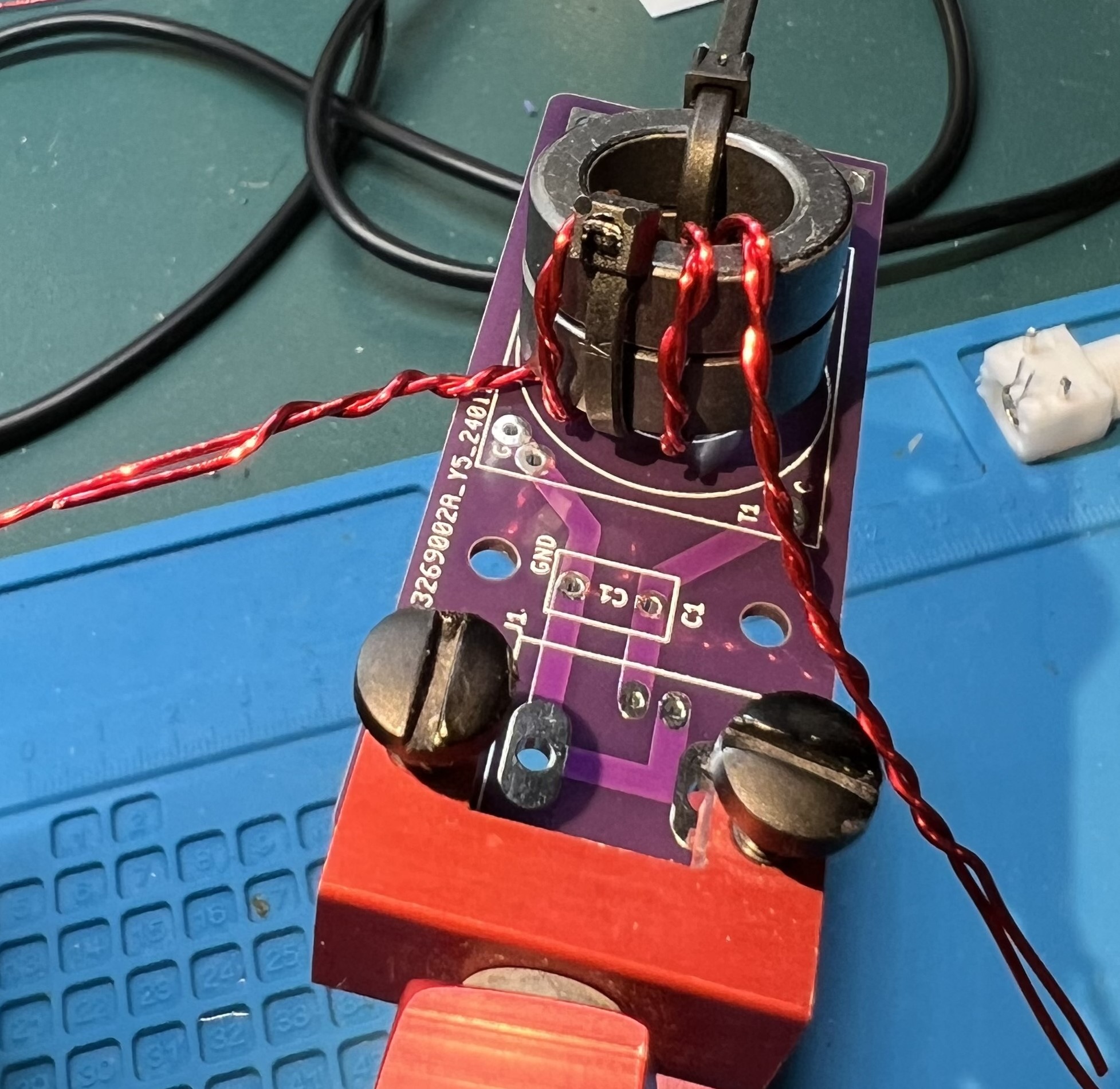
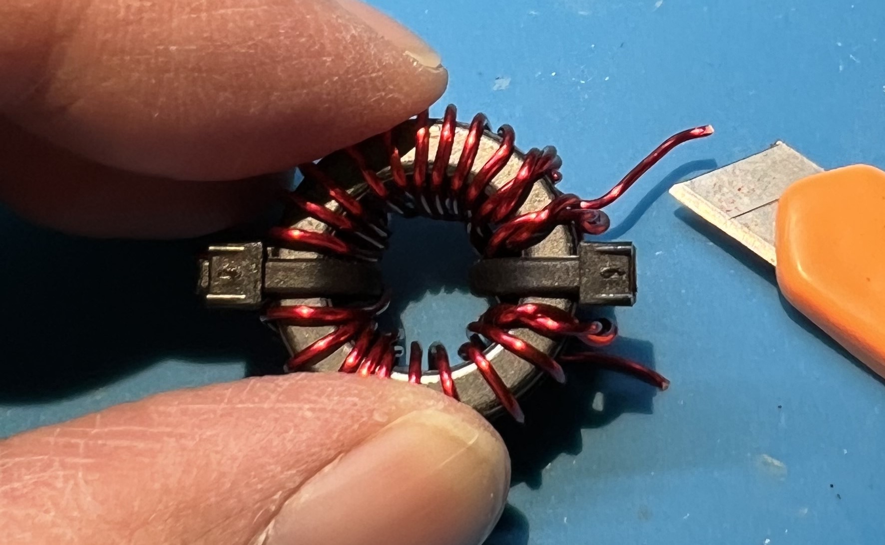
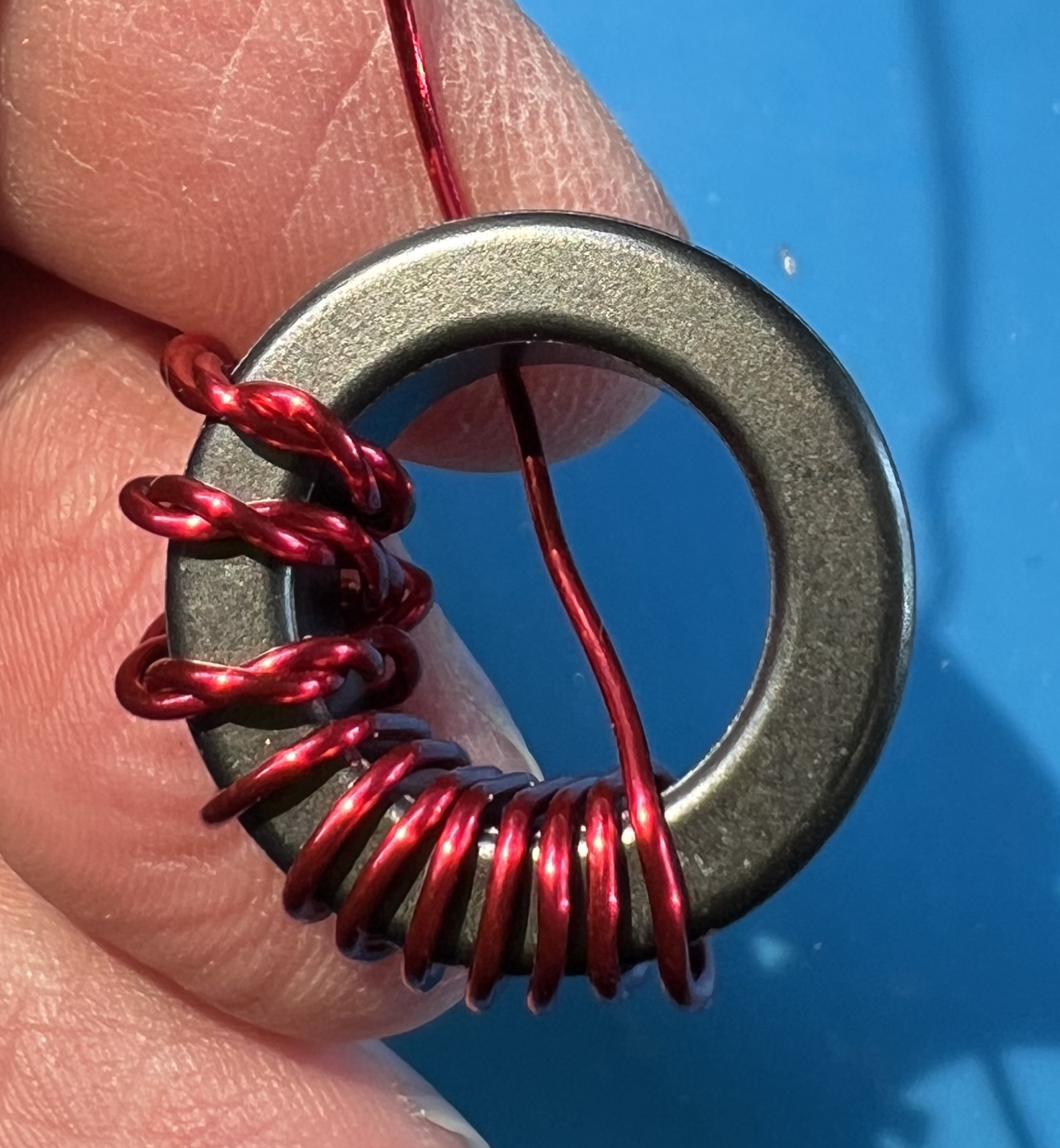
Check the twisted section against the location of the holes for the primary.
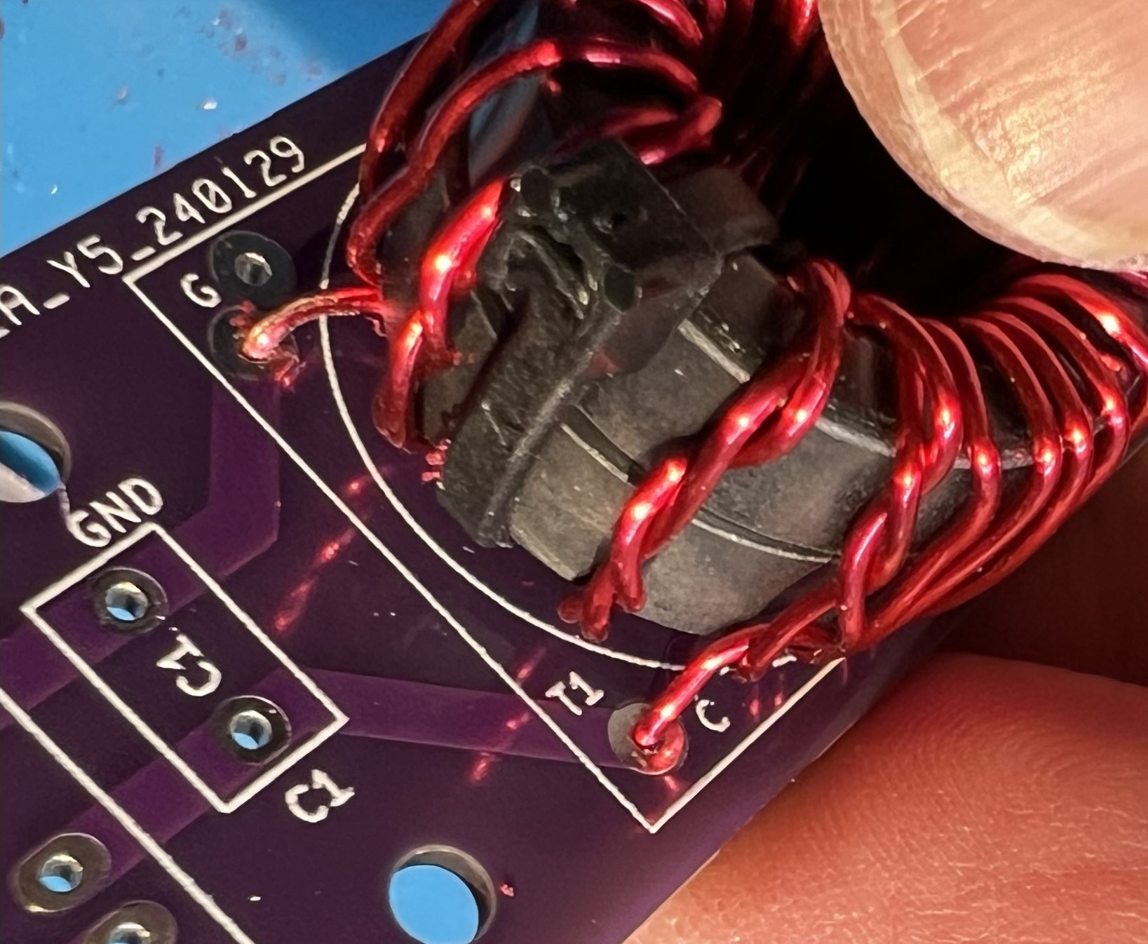
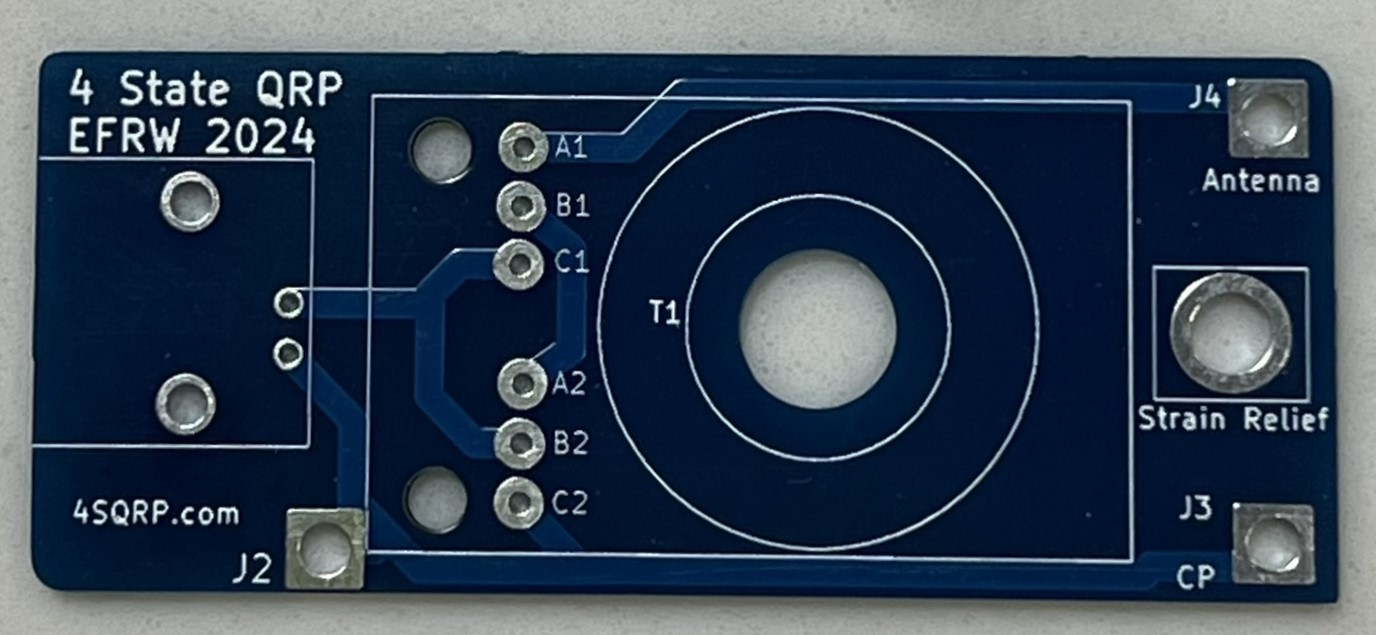
The holes are labeled G and C, inside the T1 block, near the C1 component box.
Untwist the wires as necessary so that you can cleanly reach the holes and with the other longer wire continue wrapping the secondary.
The untwisted primary that goes into the C hole and the continued counter-clockwise secondary winding.
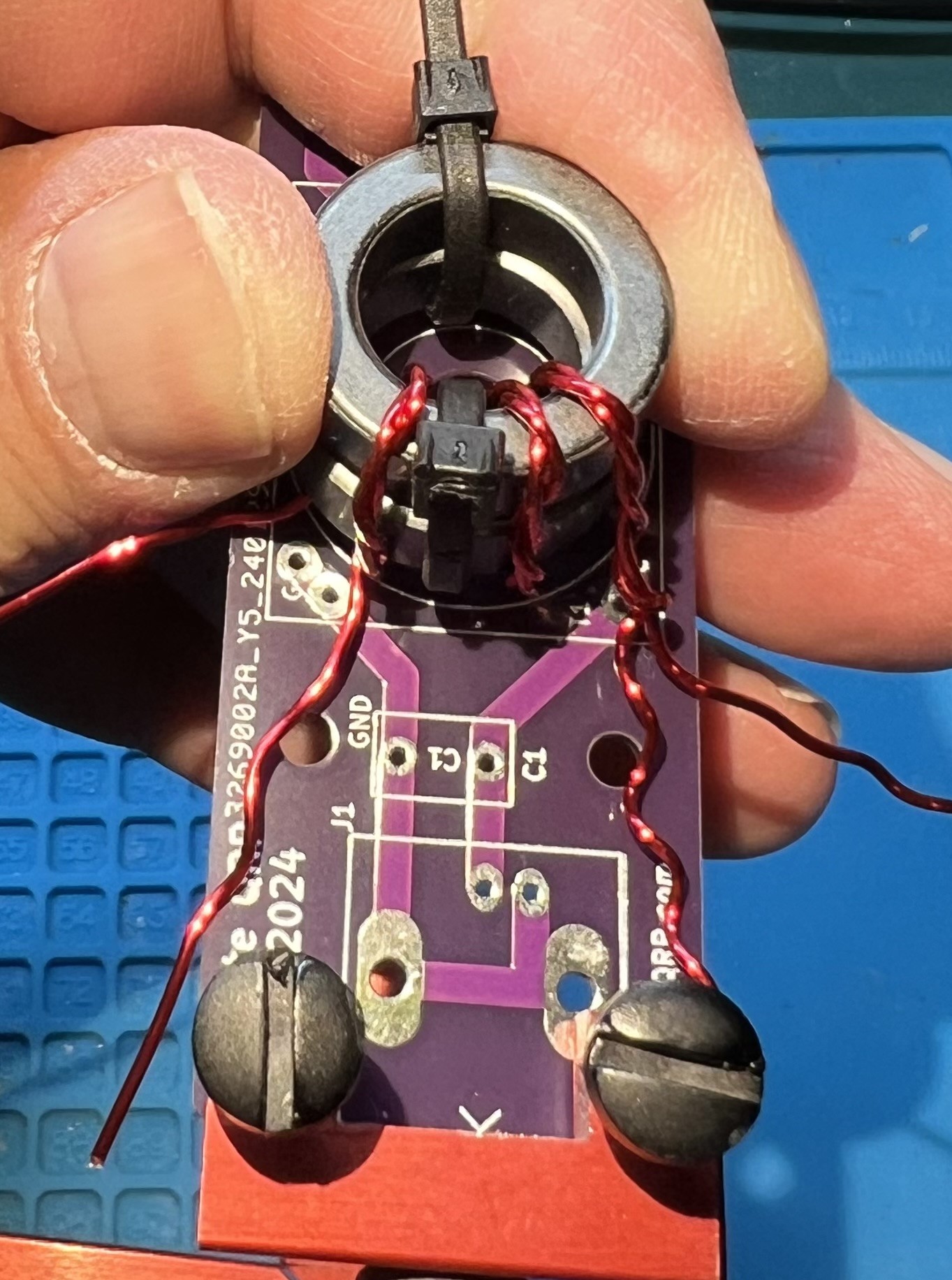
You should count from the center double wrapped wire of the primary, counterclockwise the wire passing through the center of the toroid 11 times.
That will be the middle twisted wire and one more twisted wire to the right.
Followed by 9 more turns of single secondary wire.
Now, do the same thing but continuing clockwise.
Start from the middle winding of the twisted wires.
Count it and one more twisted to the left.
Now wind 9 more to the left.
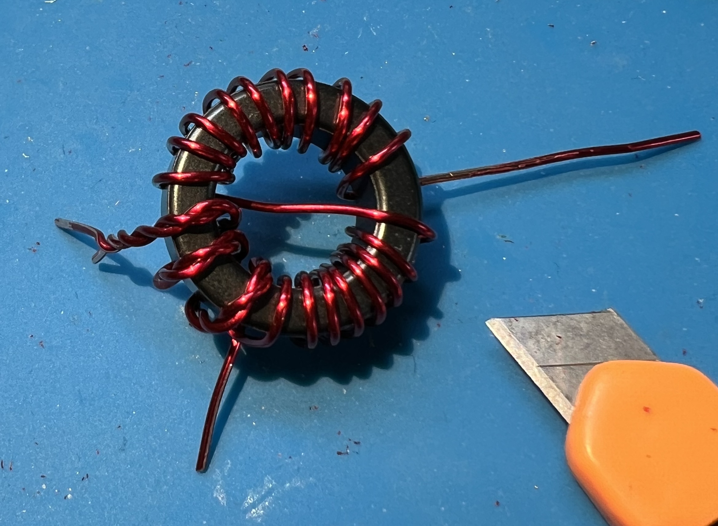
In total you will have 21 windings.
But, we counted 11 twice you protest!
Well, that’s because we counted the first winding (the middle winding) each time.
Now is a good time to give yourself a pat on the back or take a break.
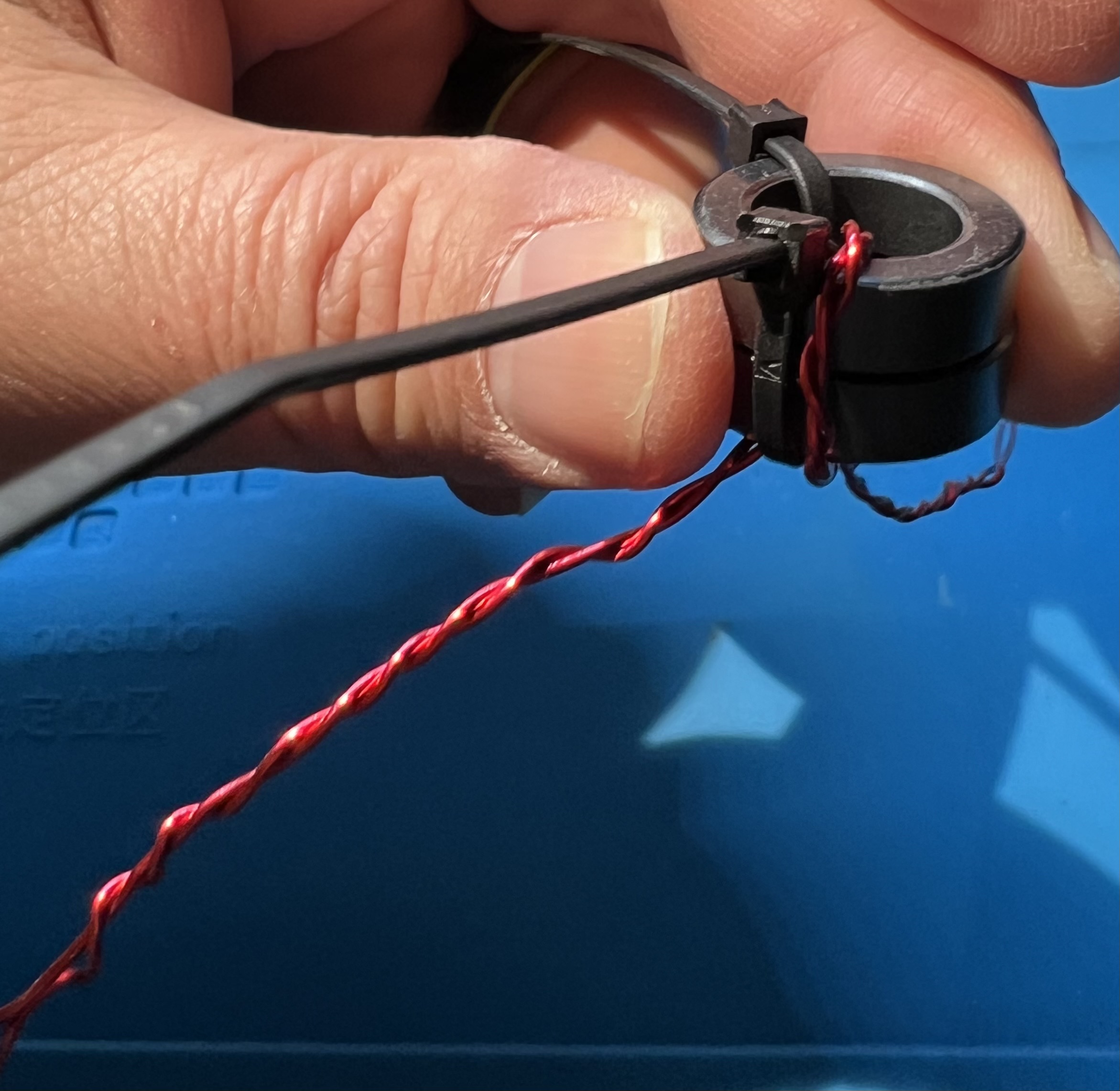
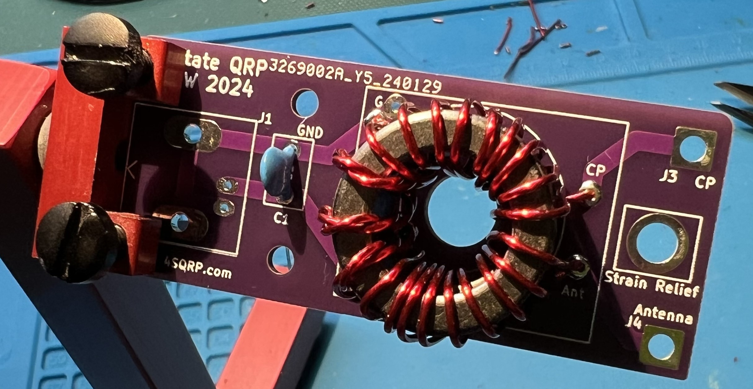
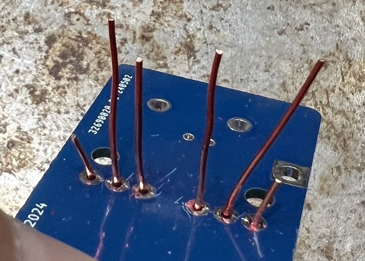
Place the prepped transformer against the board.
Line up the wires against the through holes.
Verify you can get the wires in the holes.
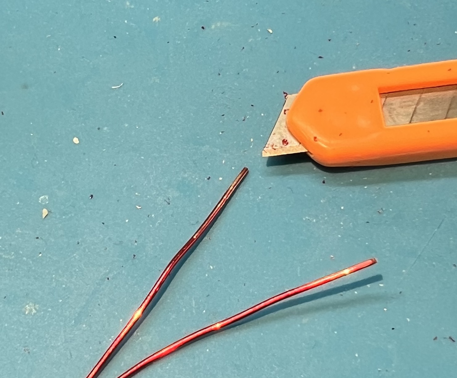
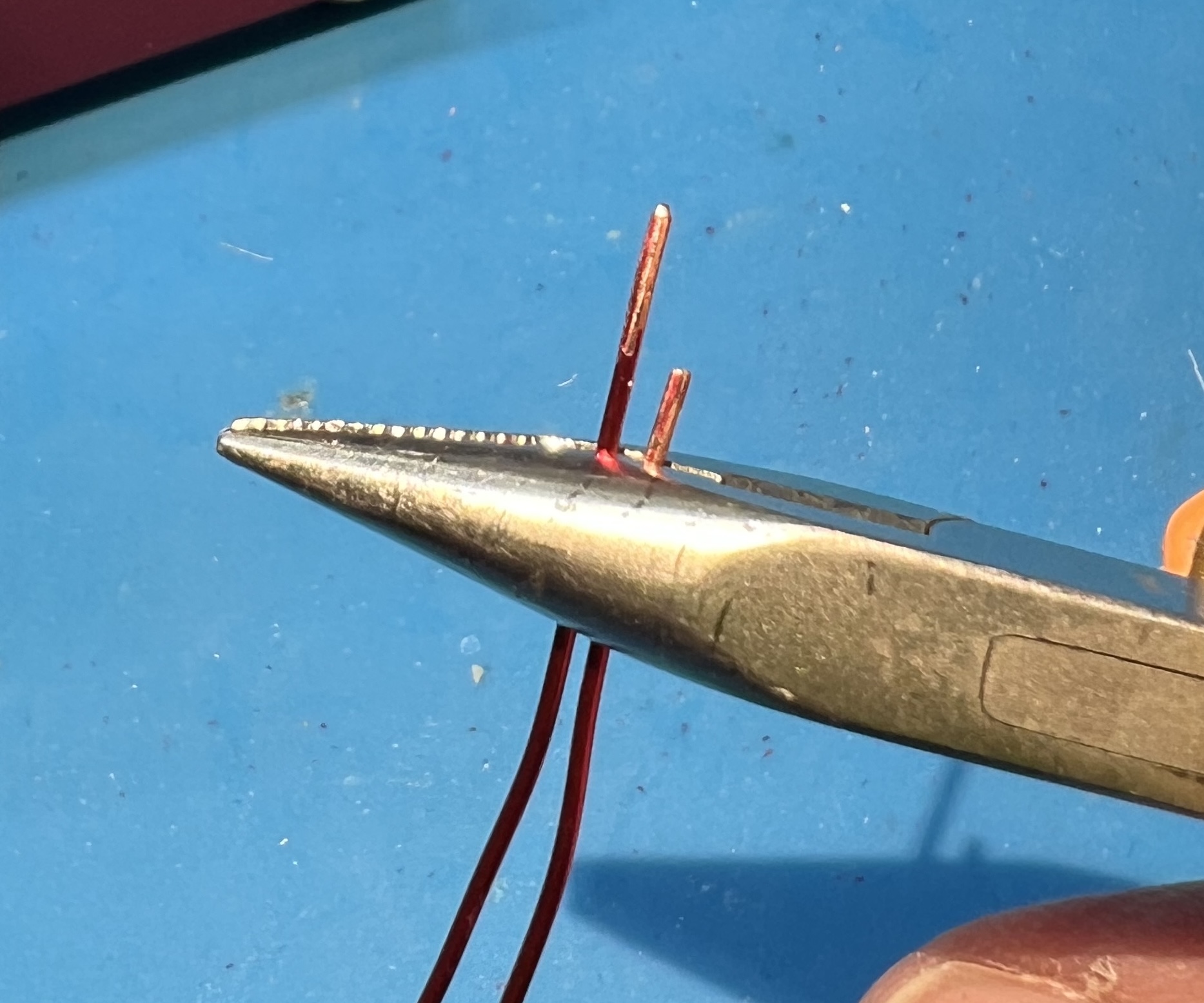
Trim the wires, but leave some excess.
Use a utility knife to remove enamel coating from the wire where you will be soldering.
I like to use a technique of holding the blade at a 45 degree angle against the wire.
Then either work the blade against the wire, or hold the blade and pull the wire.
You will need to be very careful to not nick or damage the wire itself.
Remember to rotate the transformer so that you can scrape all around the wire where it will be soldered.
Get the primary side of the transformer into position.
Get lengths and routing checked for the secondary side of the transformer.
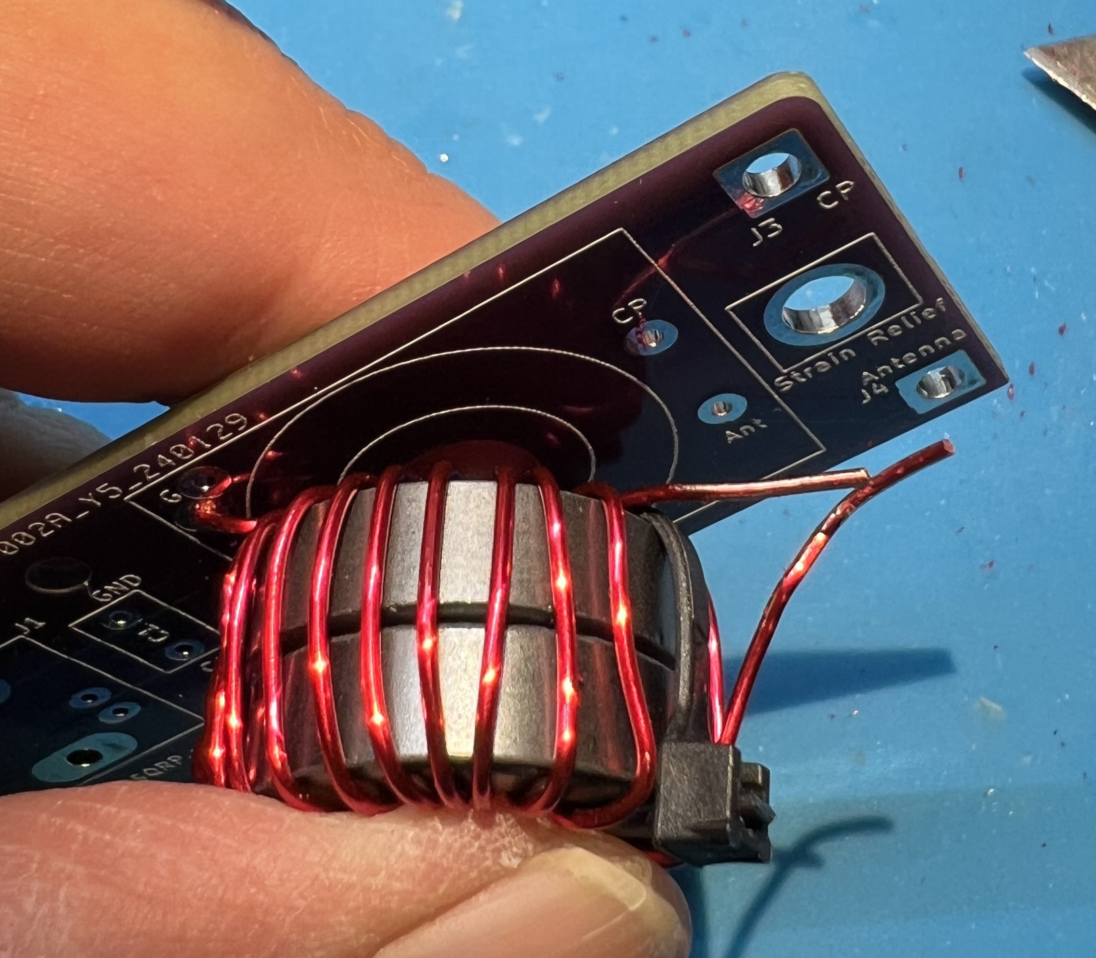
Note the bend you’ll need to get the CP end of the secondary transformer in to place.
Mini pliers can help with this.
View the transformer leads from the underside of the board.
The transformer placement viewed from above and primary side.
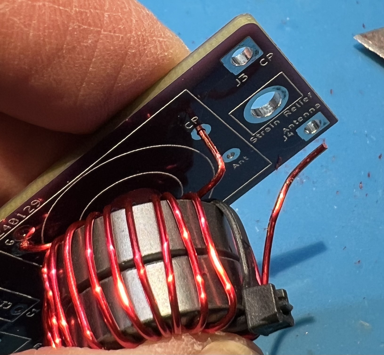
NOTE: at this time the zip ties have been removed.
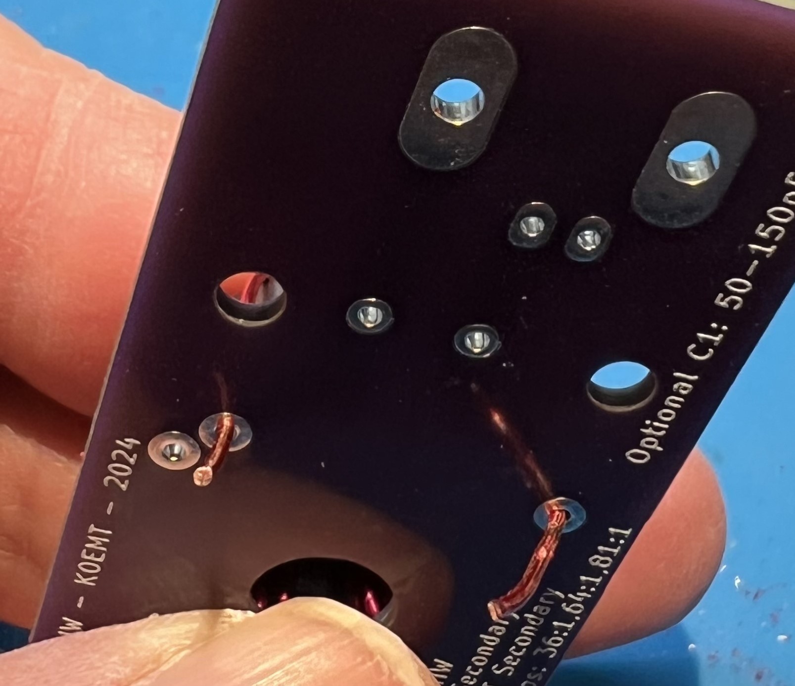
Wire leads trimmed a bit more, ready to solder.
Avoid overheating the wire and melting enamel further up into the toroid.
Note that the blue surface pictured here is a heat resistant silicone mat.
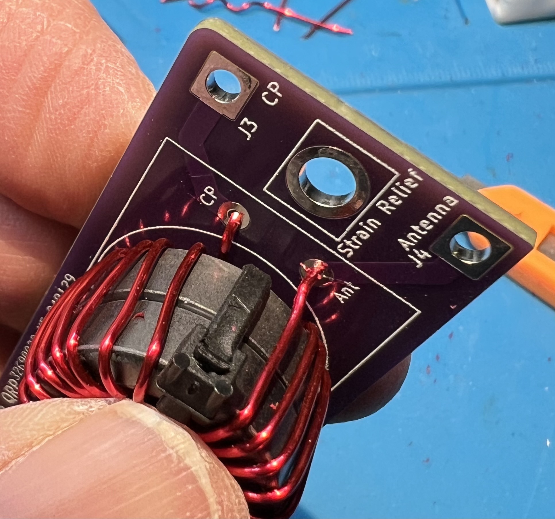
Note that the solder is covering the pad and the wire where the enamel coating was removed.
Test for good continuity on the secondary winding. Use an ohm meter to check for continuity between J3 CP and J4 Antenna on the output side.
If you don’t have continuity, that means you didn’t get the enamel off of the wire at the through holes of the secondary.
Inspect and correct wires at CP and Antenna in the transformer block.
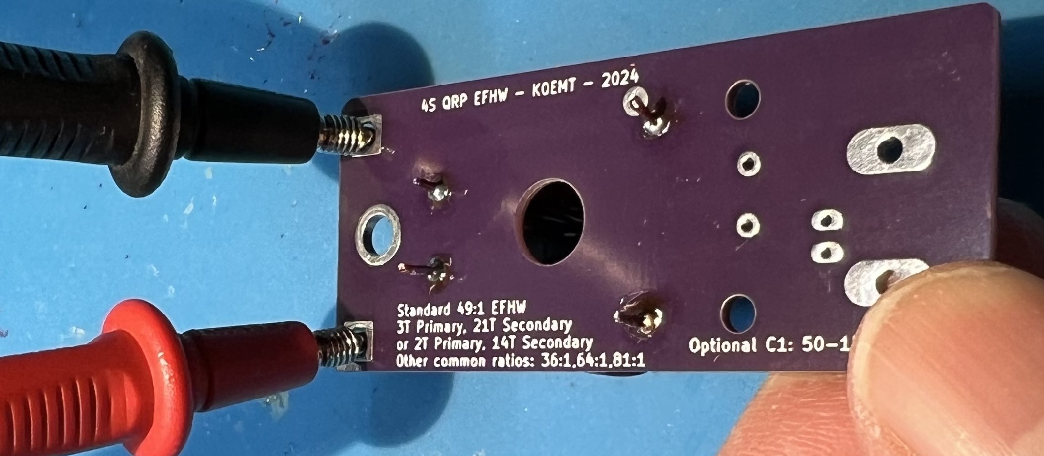
Check for continuity between the BNC mount holes and the secondary side CP and Antenna connections.
You should not have continuity here.
If you do have continuity, that means you have somehow shorted the primary and secondary wires.
You will most likely need to remove the windings and restart with new wire.
Flip the board over and test for continuity in the capacitor block C1. You should have continuity when you place your leads here. If you don’t have continuity, that means you didn’t get the enamel off of the wire at the through holes of the primary. Inspect and correct wires at G and C in the transformer block.
Trim leads.
Solder the capacitor in place now.
Solder the BNC in place now.
Use a spudger to spread the transformer turns both inside and around the core.
The spudger is plastic and is used to avoid damaging the wire or the enamel coating.
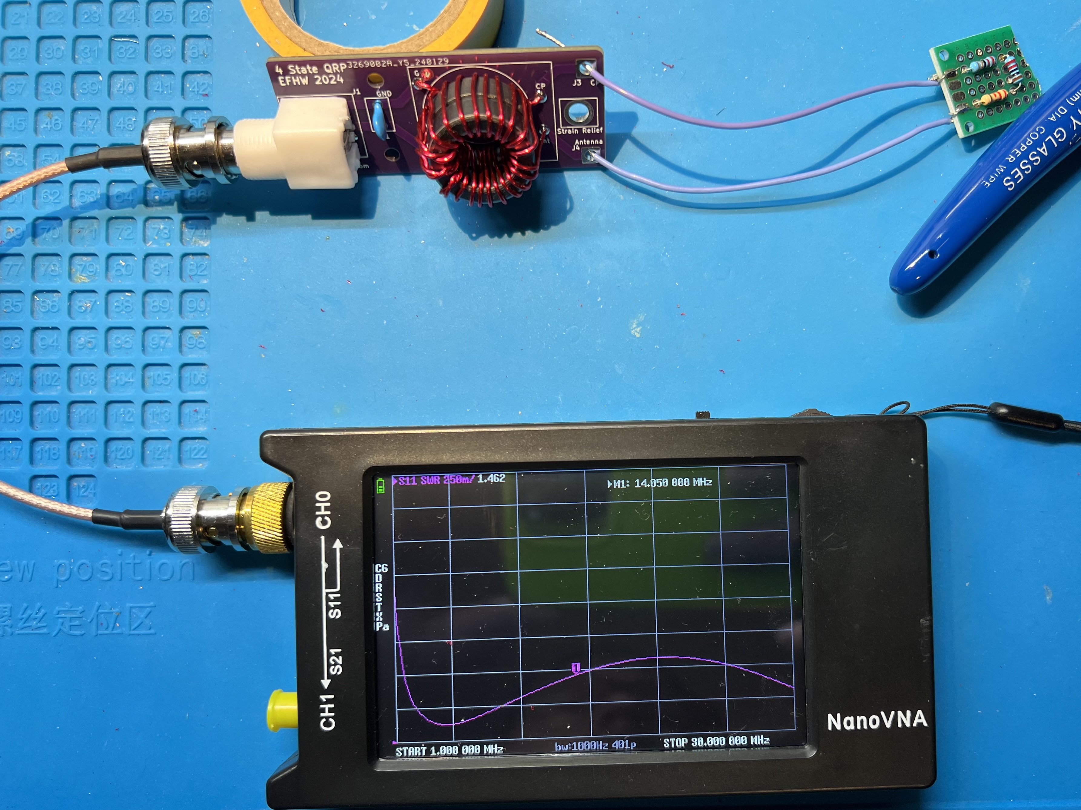
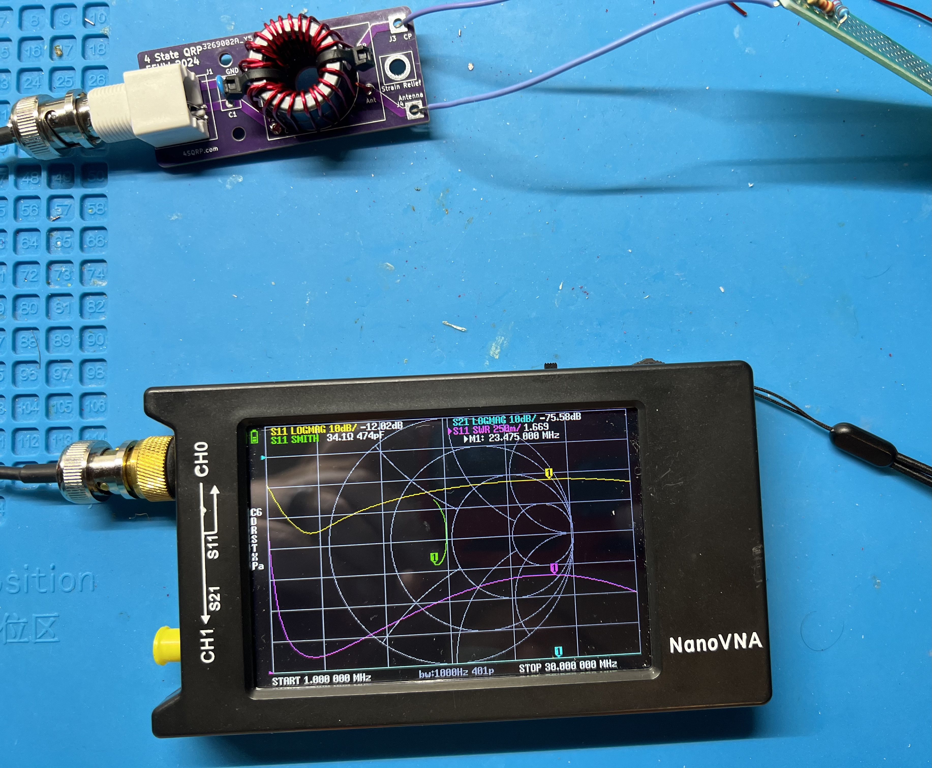
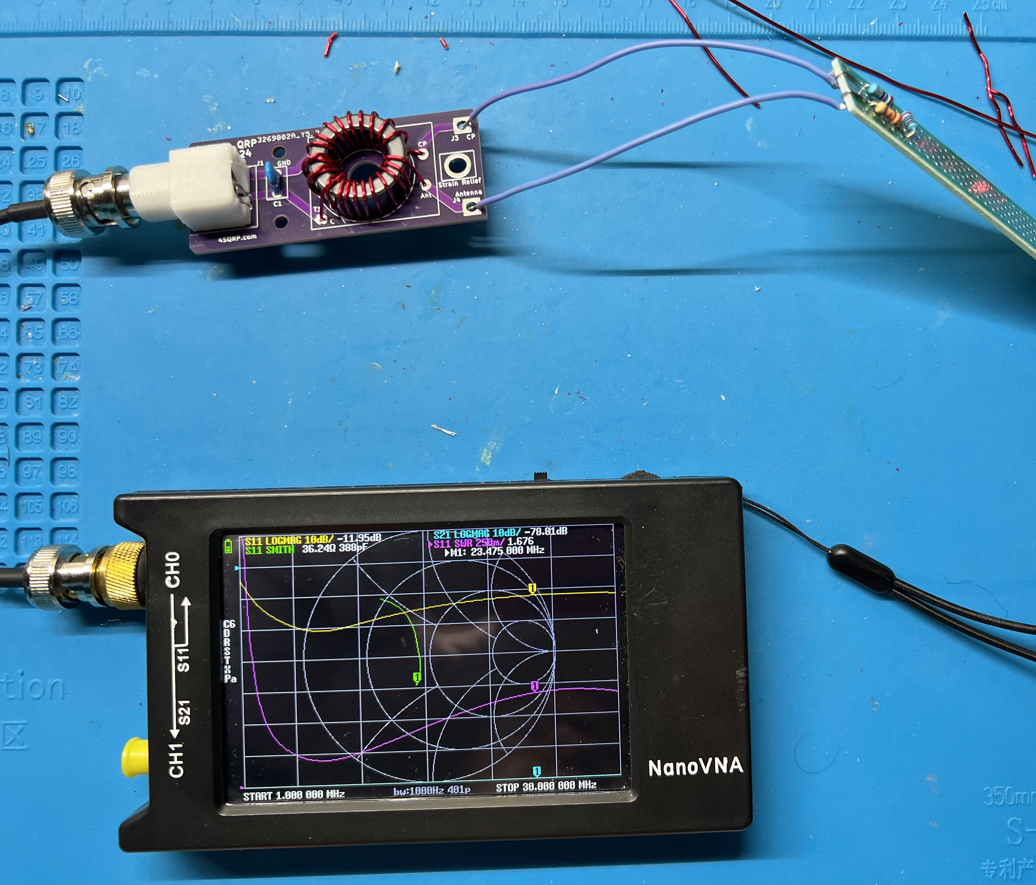
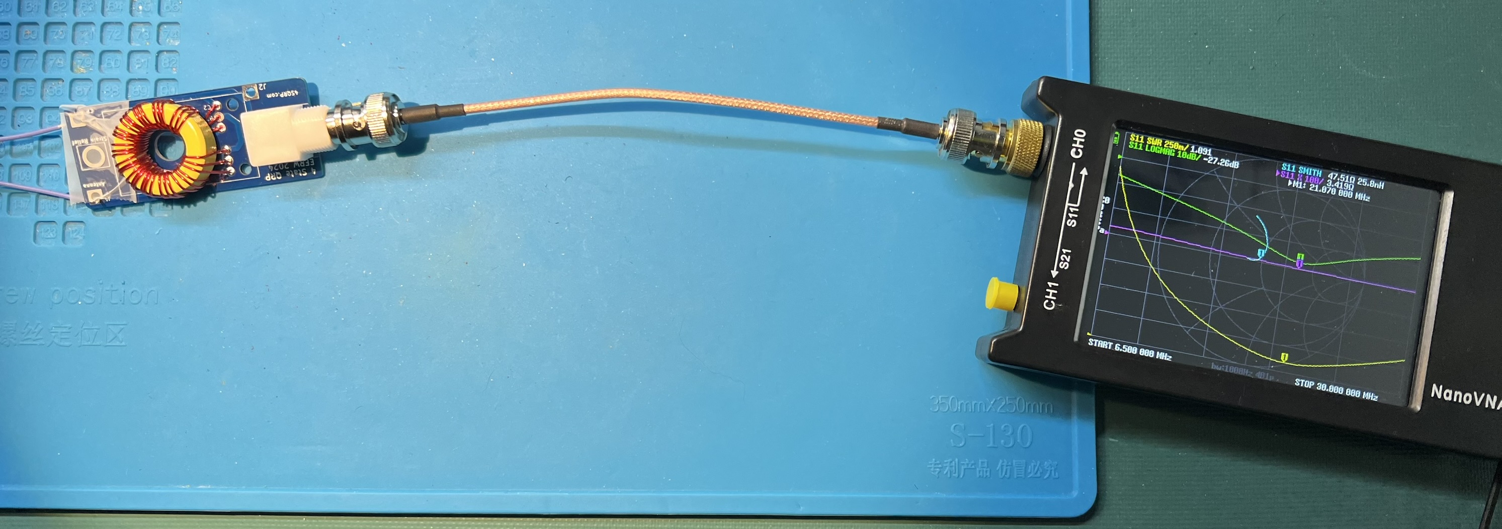
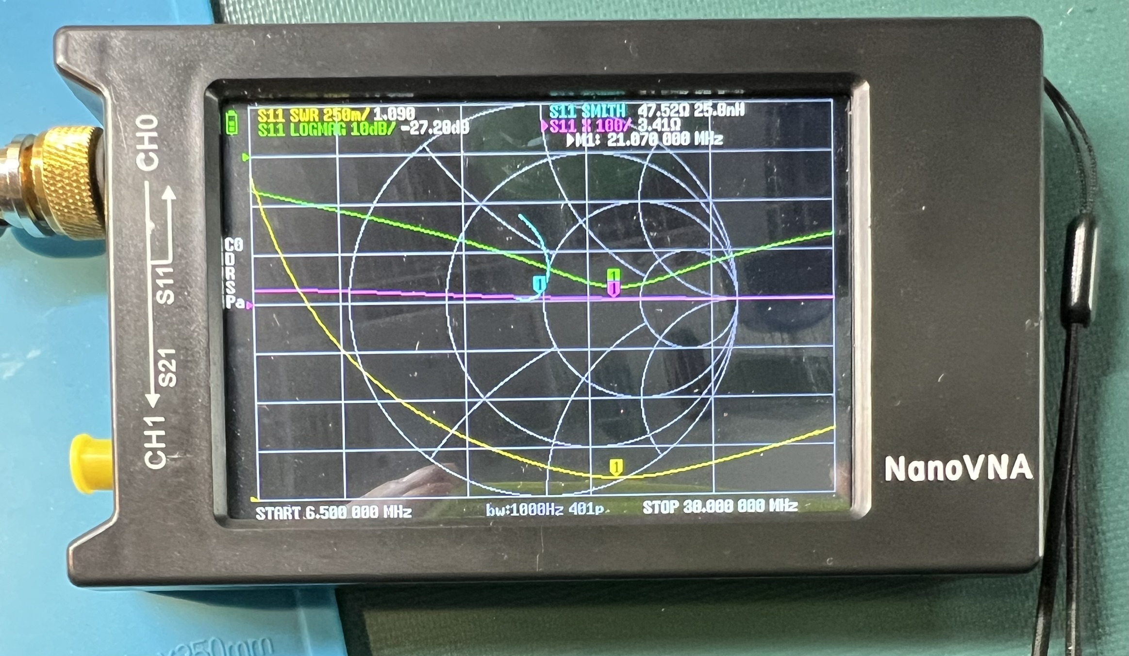
Transformer with a resistive test load and a nanoVNA showing SWR plot.
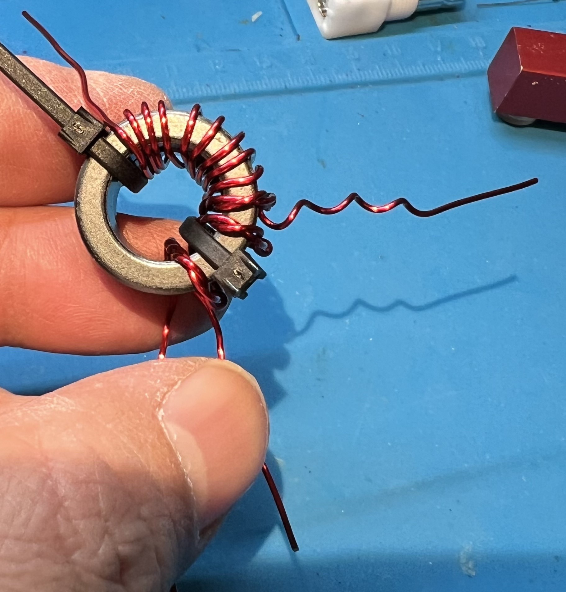
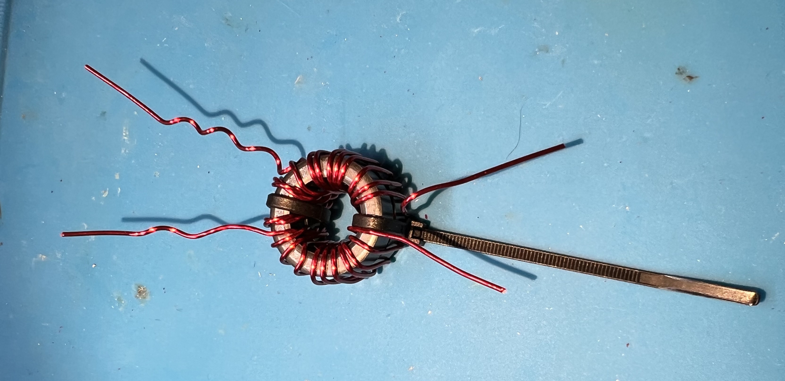
Use 20awg enamel coated wire. Use the same assembly approach as with the double stack. However, with a single toroid, the Primary has 4" of wire, and the secondary uses 20" of wire. The twisted section will be a bit over 3" in length.
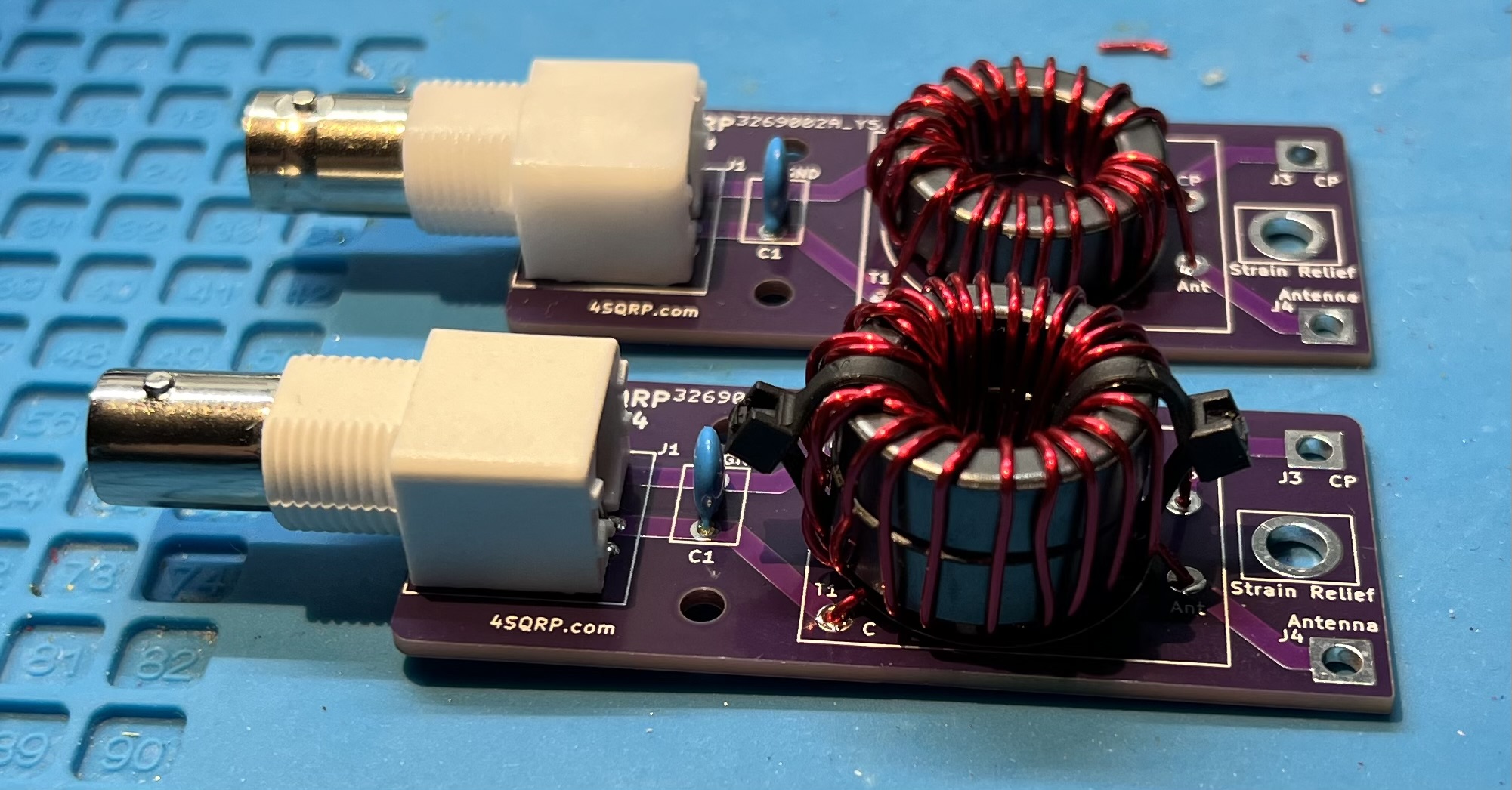
Uses the same lengths of wire for single or double stack configuration.
Prepare the wire ends.
Slightly offeset the end of the twisted pair.
The twisted section will be a bit over 3" in length.
Wind onto the core in a counter-clockwise fashion.
Cross over the core at turn 11.
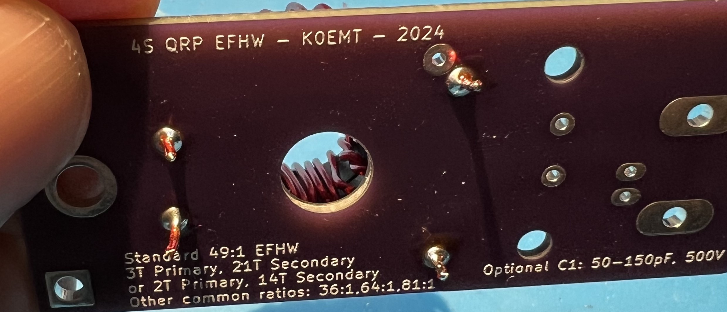
Remove the enamel from the wire where it will be soldered.
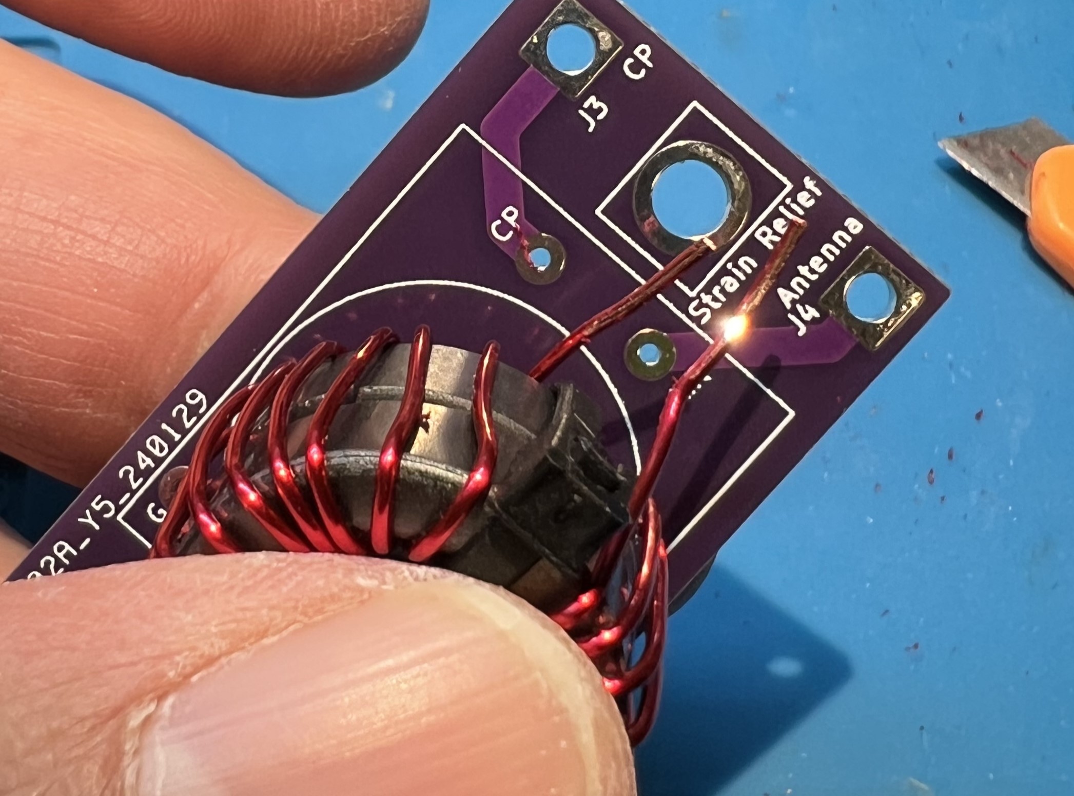
Solder the primary side wires. You will also solder the ground side of the secondary at this time.
Make a wire jumper to connect from the G pads in the toroid block over to the CP pad.
You may consider soldering this ground jumper in at the same time as the primary and secondary grounds.
I ended up soldering the jumper at the CP pad on both the top and bottom of the board.
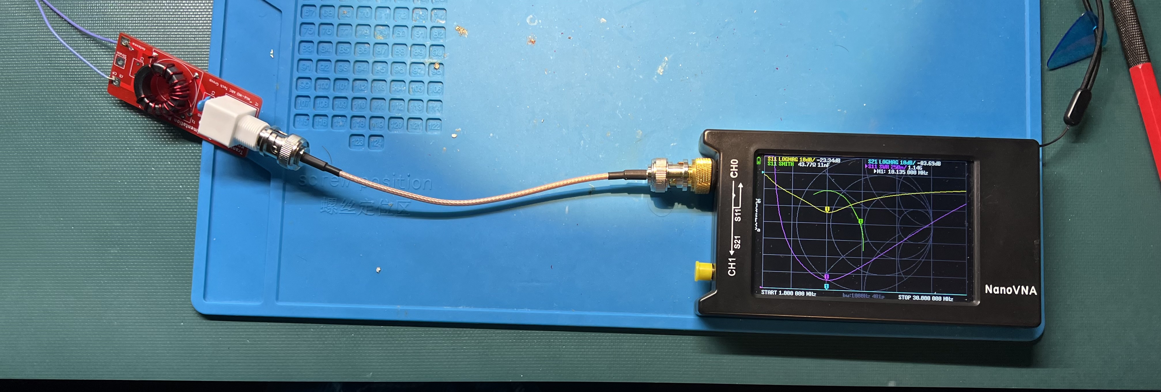
Checking the completed board with a nanoVNA.
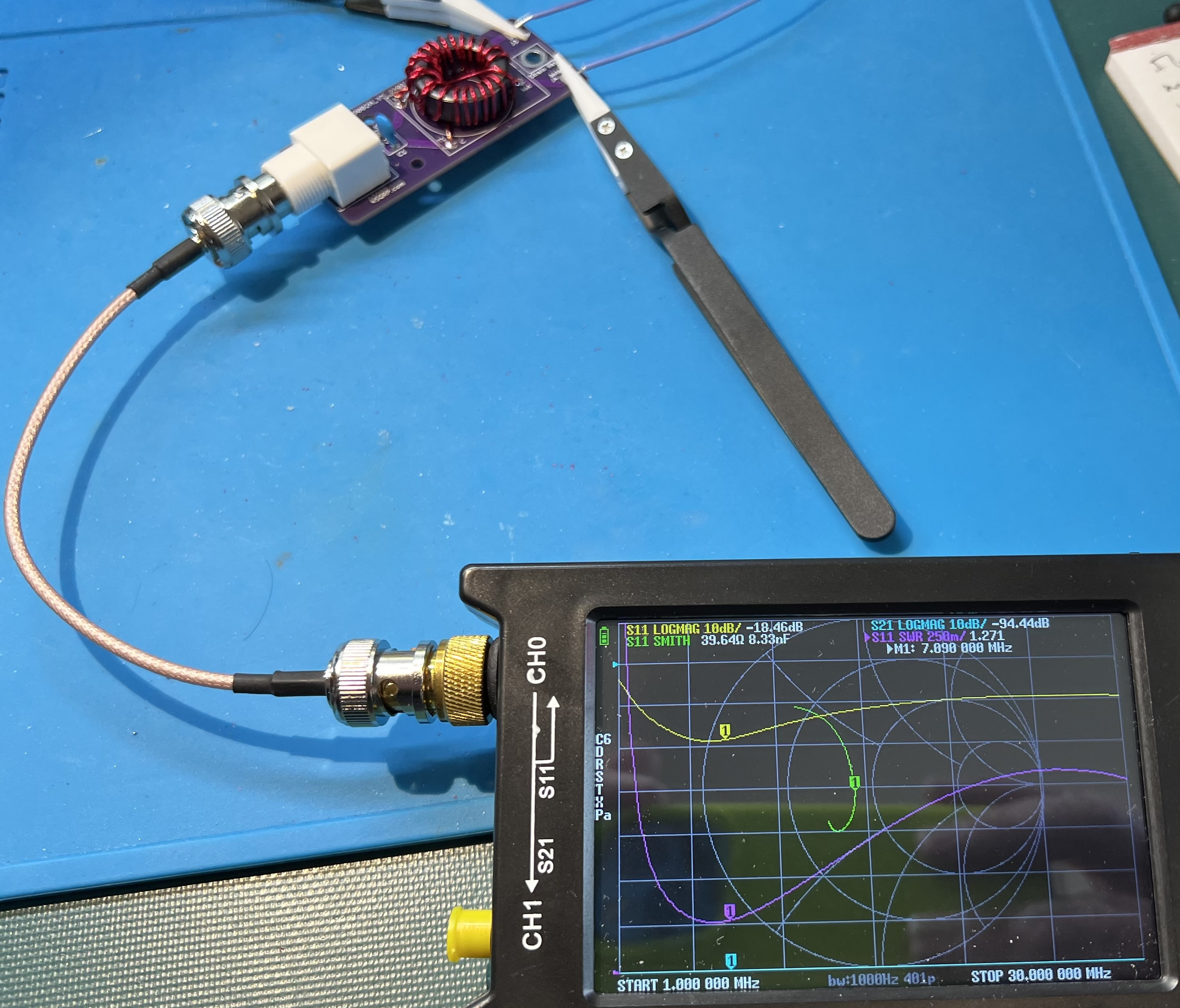
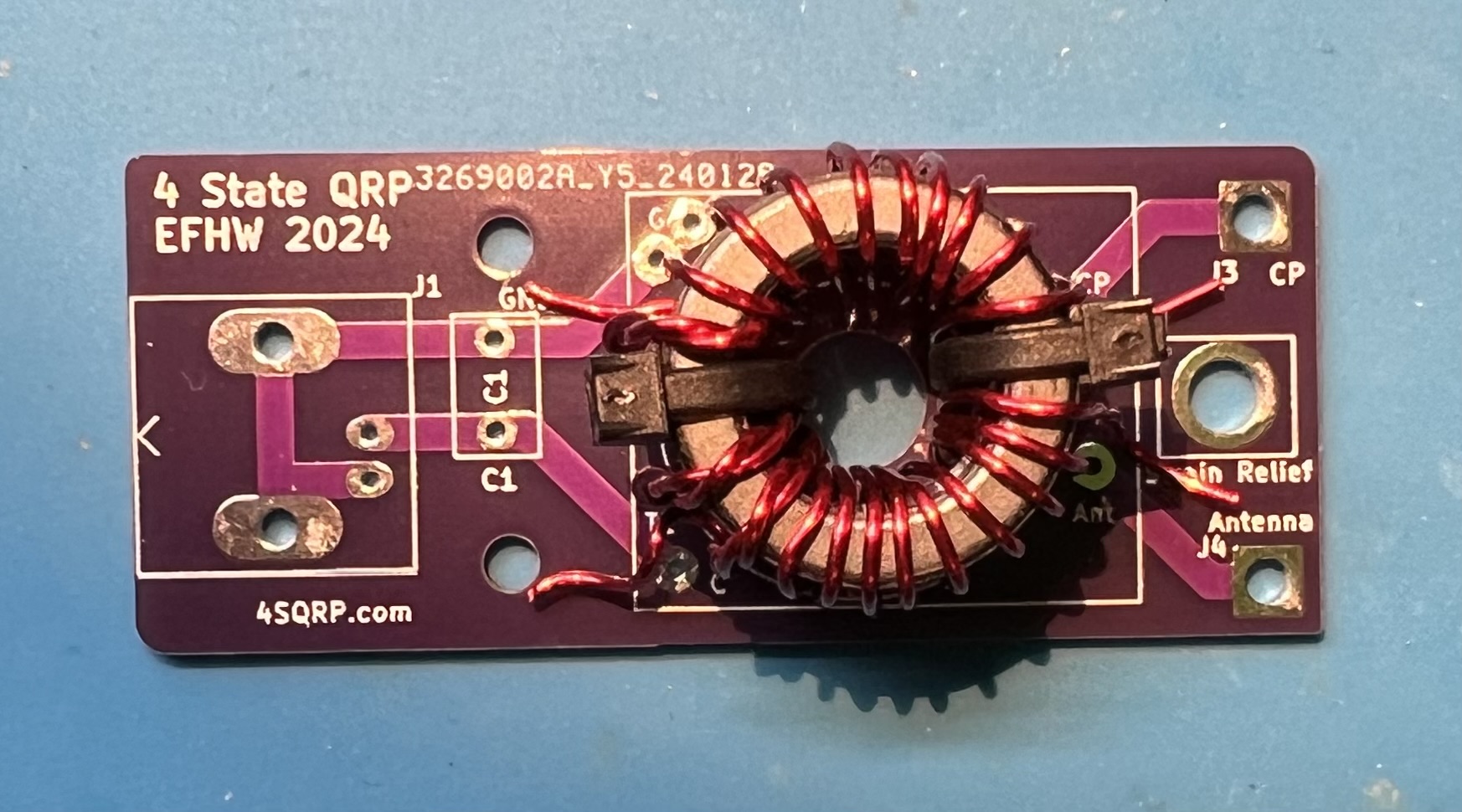
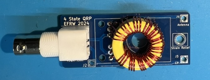
The completed board.
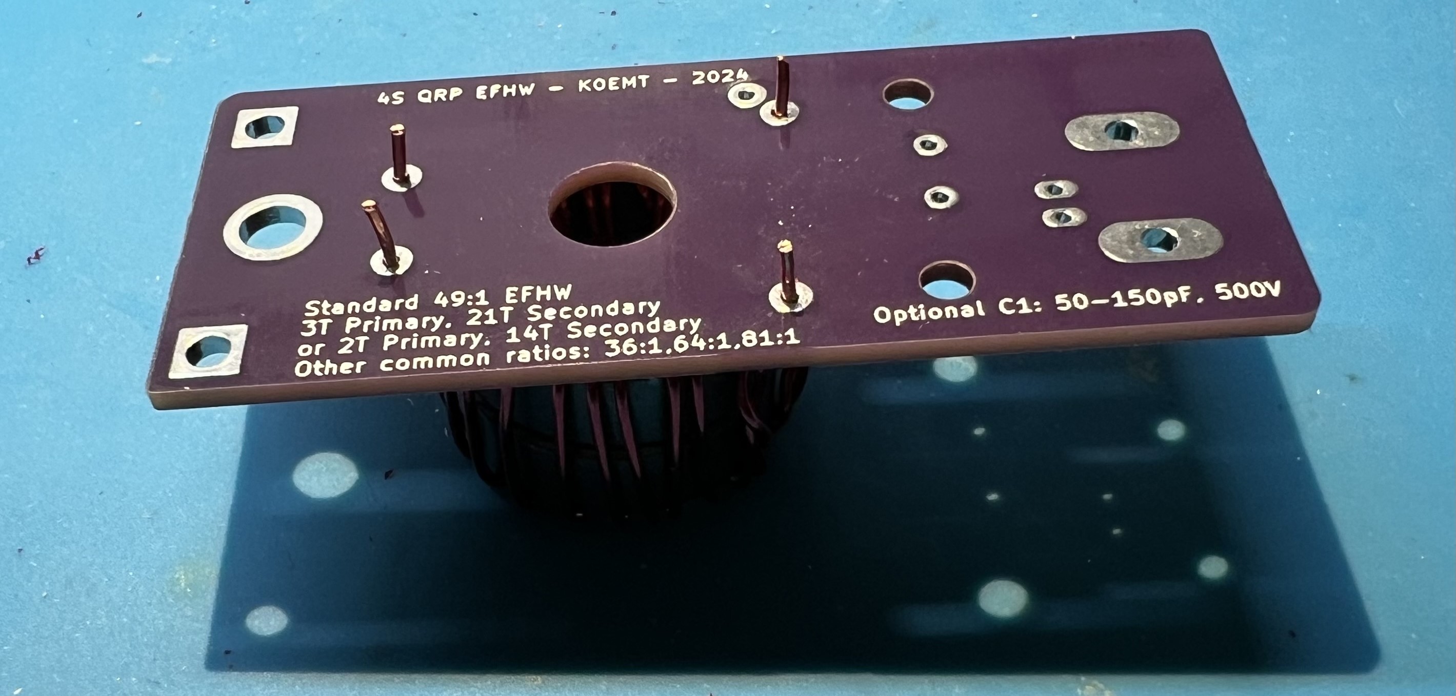
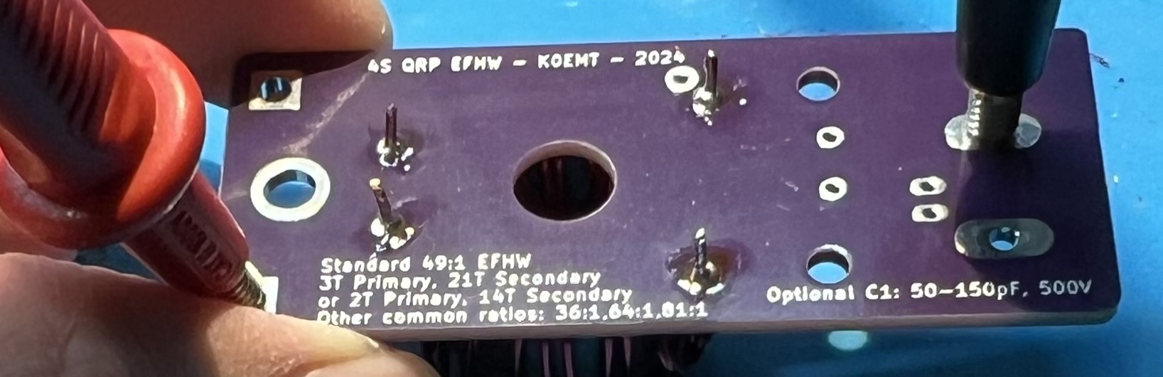
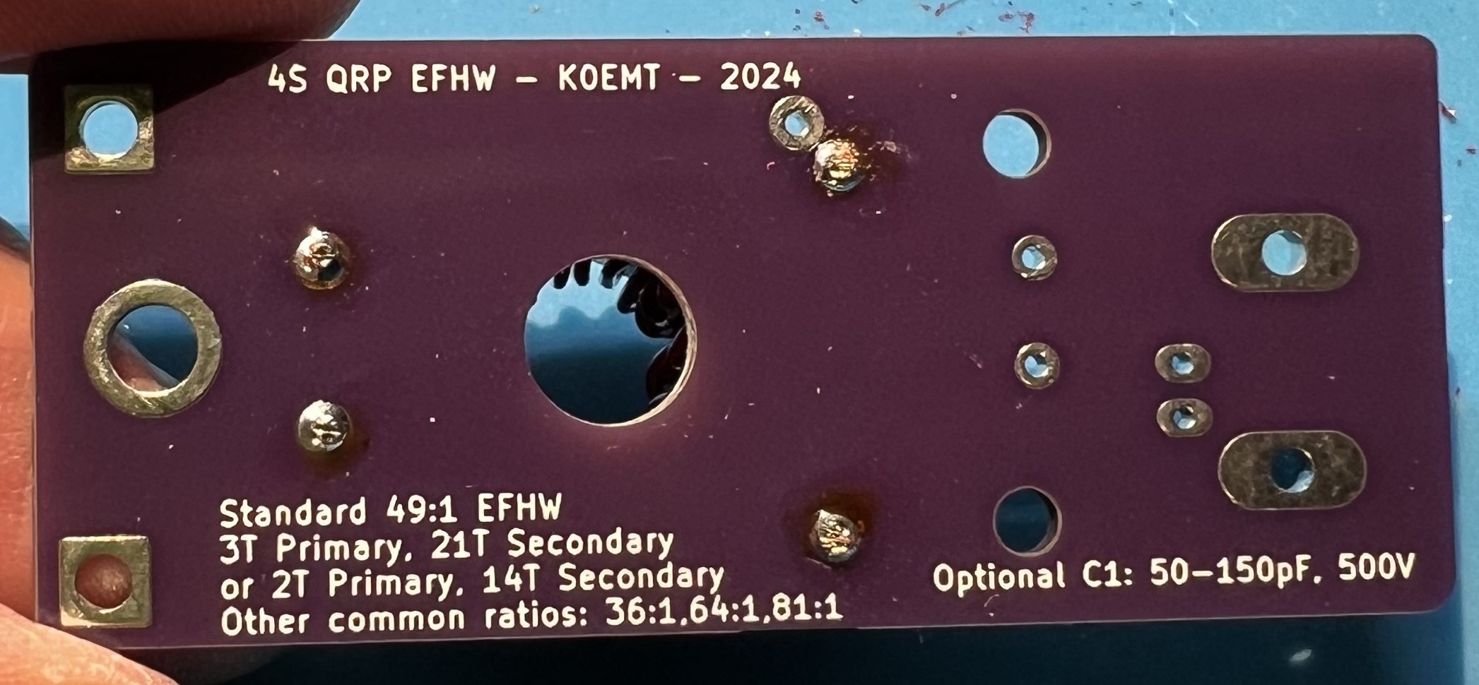
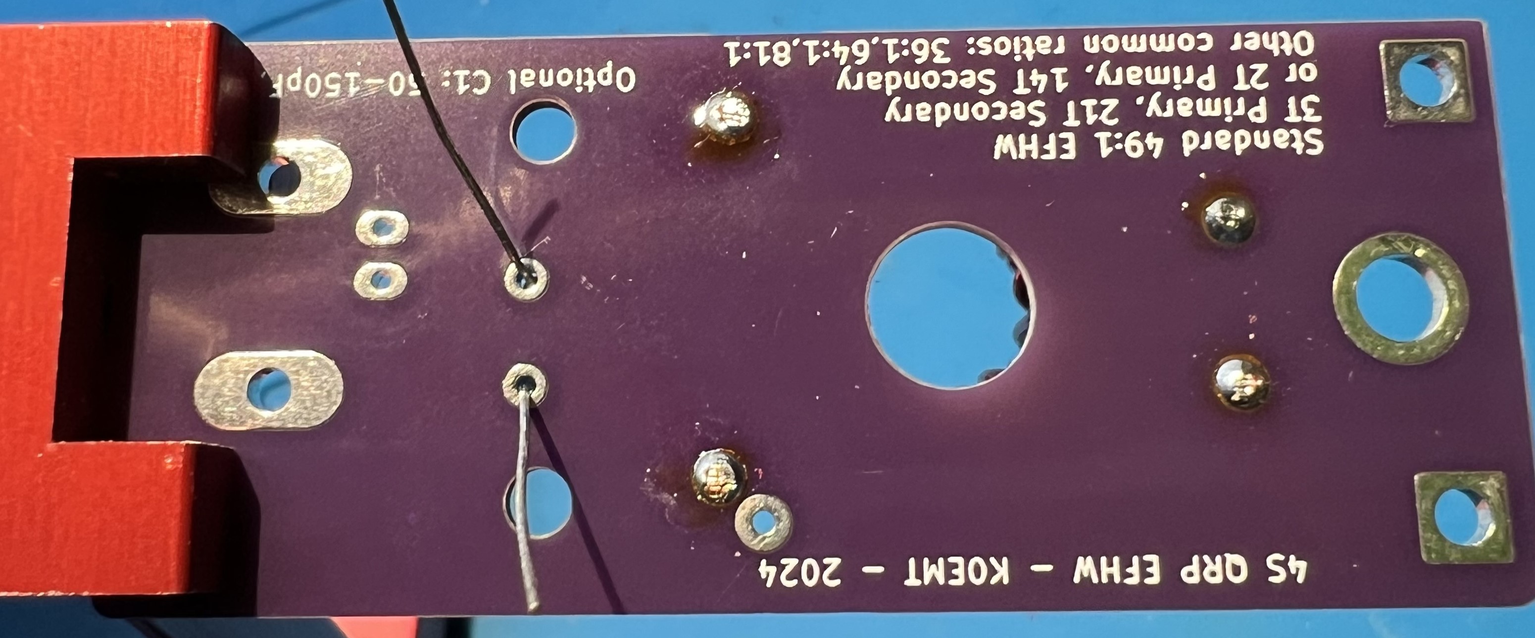
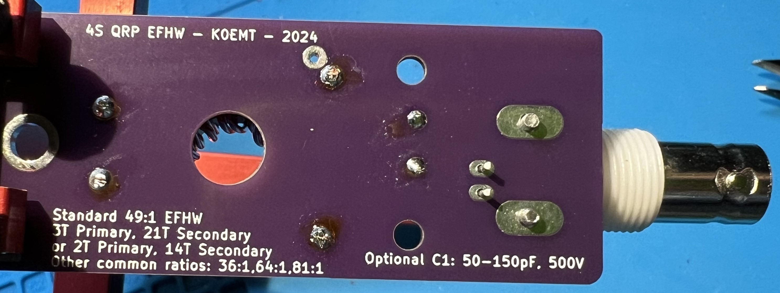
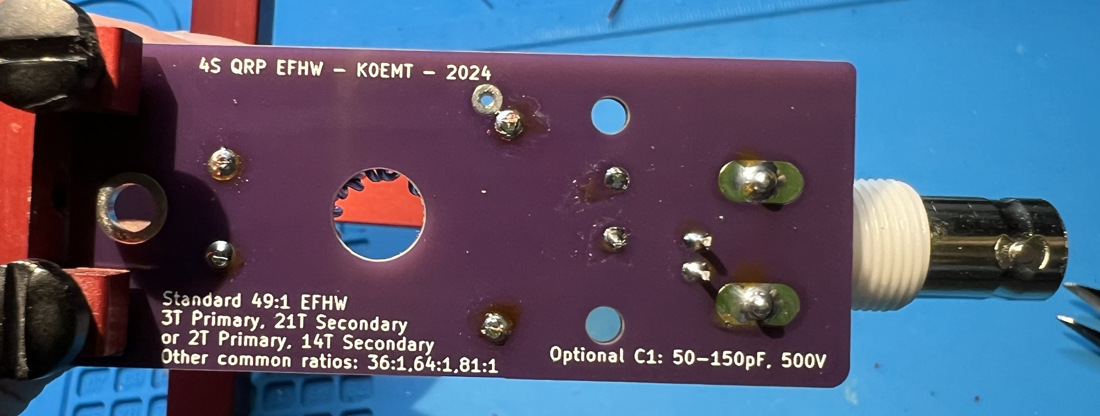
When you see a notation like 2:14 and 3:21 that means how many turns on the primary and how many turns on the secondary part of the transformer. 2:14 means 2 turns on primary, 14 turns on secondary. Likewise, 3:21 means 3 turns on primary, 21 turns on secondary.
So, where does the 49:1 come from? That is the transformation ratio. To arrive at it we consider the ratio of turns on the secondary to the primary. With a 2:141 this becomes 14 to 2 or 7 to 1. Take the 7 and square it to arrive at 49:1. We’re transforming a roughly 2450 ohm feedpoint down to 50 ohms.
Other common ratios that are used with EFHW antennas are 36:1, 64:1, and 81:1. Respectively ratios of 6:1, 8:1, and 9:1. To make a 36:1 transformer you could have a 3 turn primary, and an 18 turn secondary.
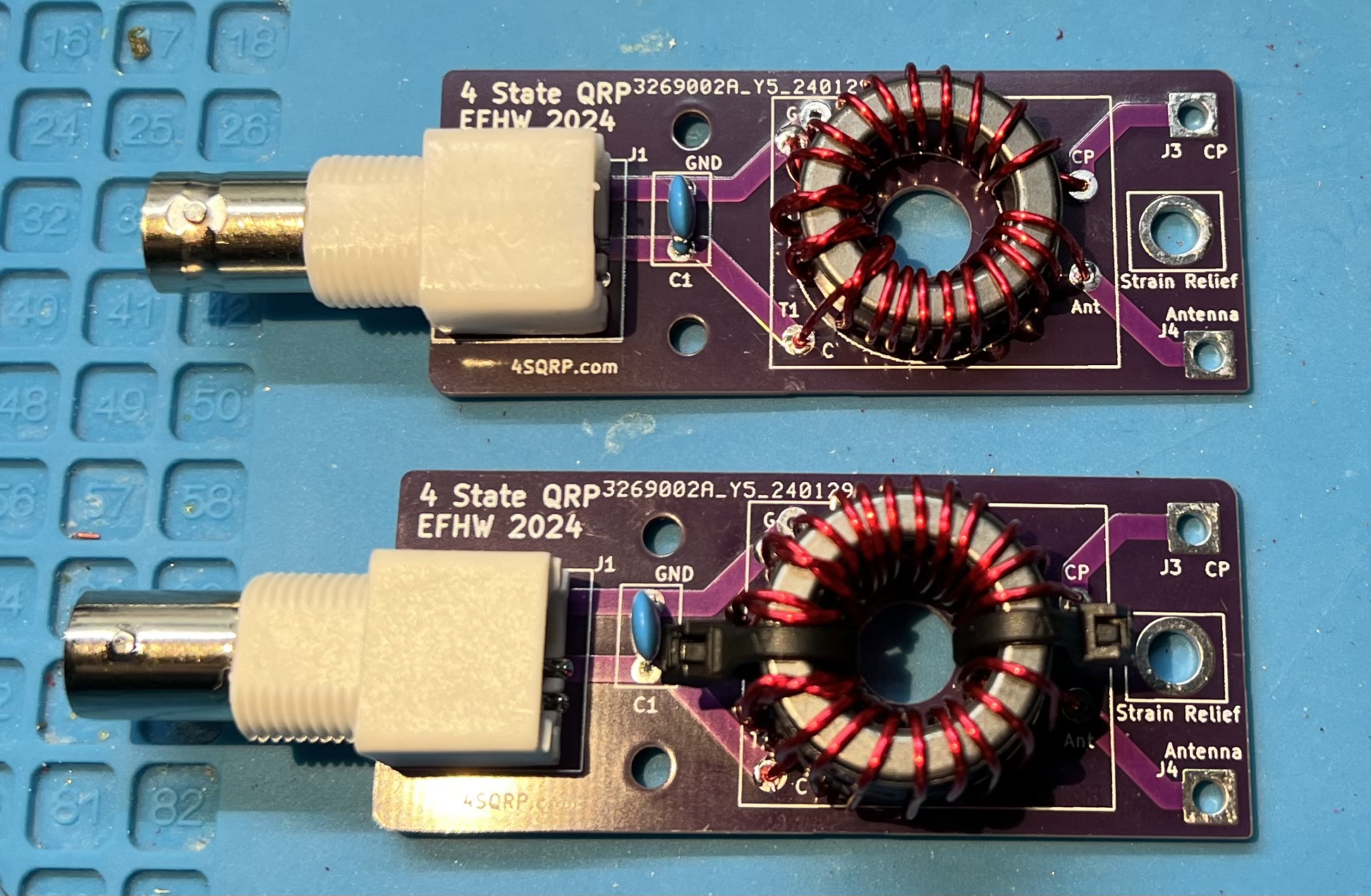
Note: In these pictures, they are all 49:1 transformers.
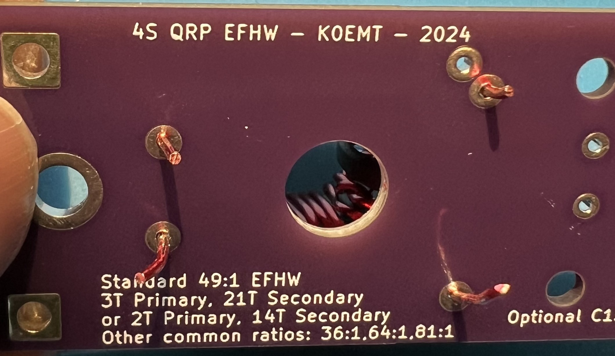
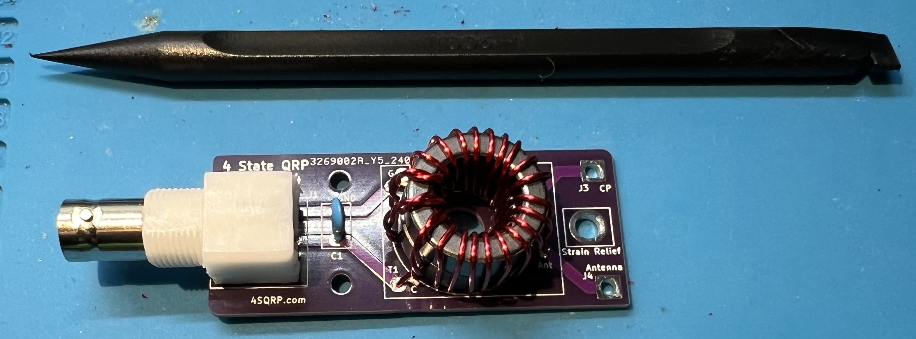
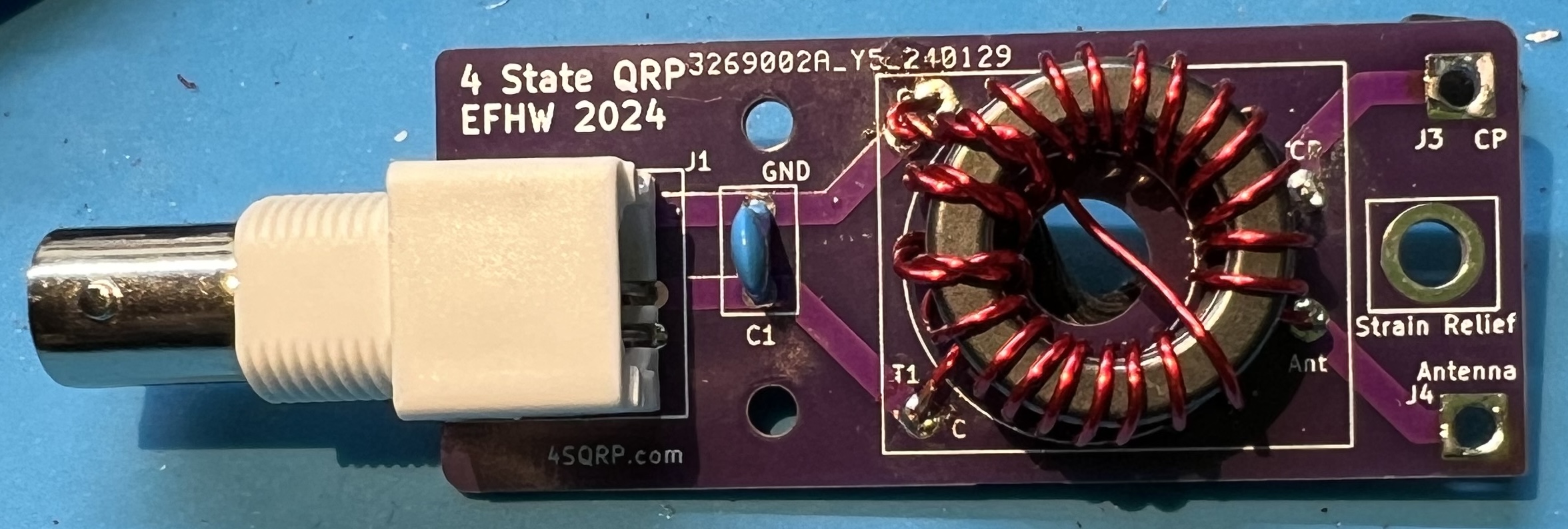
Original 4S QRP Experimenter PCB 2:14
Original 4S QRP Experimenter PCB 3:21
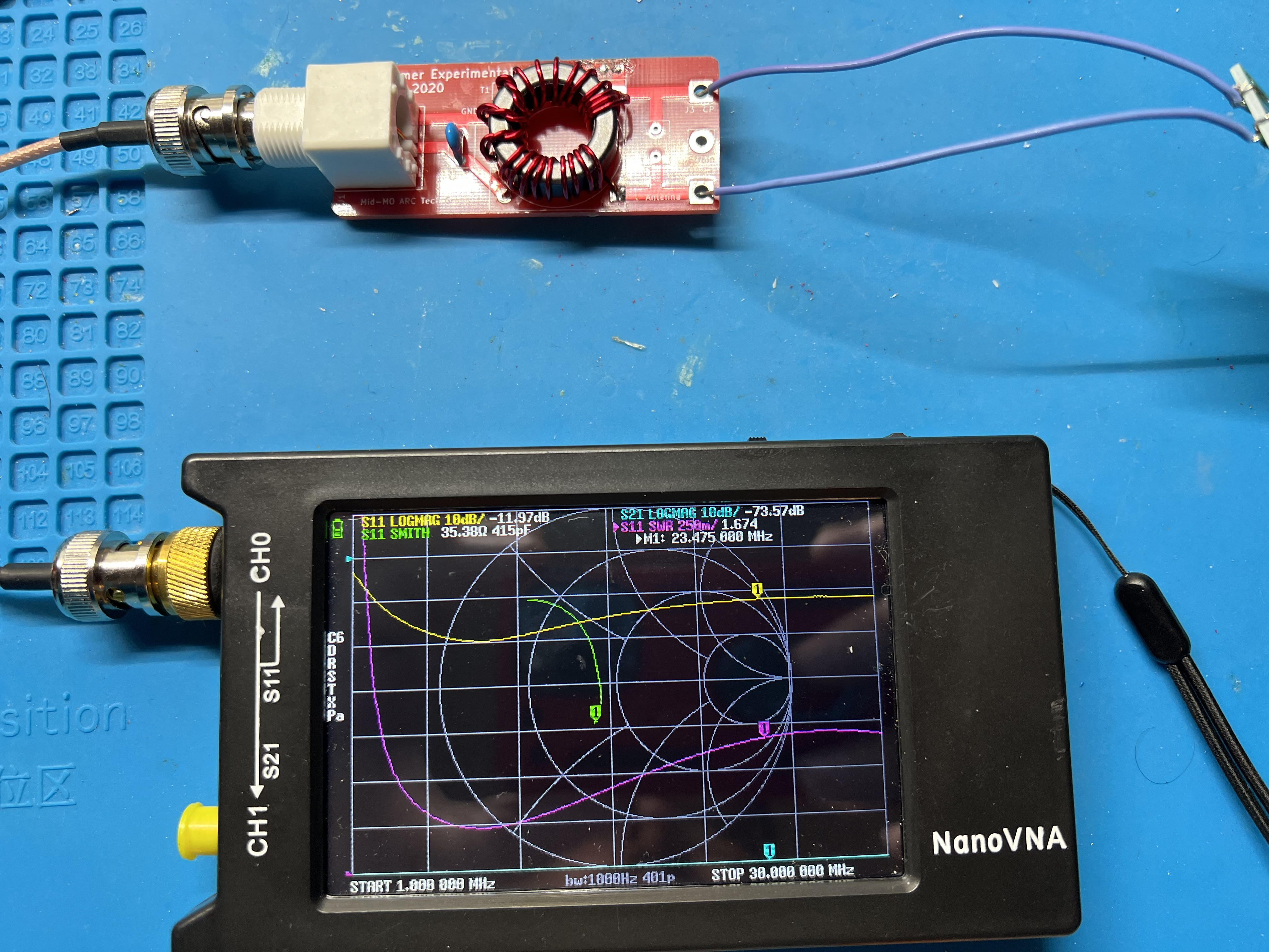
2024 EFHW board with Double Stack FT82-43 toroids, 3:21
2024 EFHW board with Single Stack FT82-43 toroids, 3:21
The 100pF capacitor is often added to the primary side of the transformer in an End Fed Half Wave (EFHW) antenna for a couple of reasons:
Improves Higher Frequency UNUN Performance: The capacitor can help improve the performance of the Unbalanced to Unbalanced (UNUN) transformer at higher frequencies2,3.
Compensates for UNUN Primary Leakage: The capacitor can help compensate for any leakage in the primary of the UNUN2.
Flattens SWR at Higher Frequencies: The addition of the capacitor can help flatten the Standing Wave Ratio (SWR) at higher frequencies2. This is particularly noticeable for frequencies above 20 meters2.
It’s important to note that the specific impact of the capacitor can depend on the bands you are interested in. For instance, if you’re building an antenna for the 40m band, you might not need the capacitor. But if you’re also using the 20m band, the capacitor can be quite beneficial4.
Please note that these are general observations and the actual impact can vary based on specific antenna designs and operating conditions. It’s always a good idea to experiment and see what works best for your specific setup2,4.
Does the antenna system need a counterpoise? There is always one present. With end fed antennas you also need to watch out for common mode current (CMC) on the feedline.5
Primary Source: Conversation with Bing, 3/20/2024
An end fed half wave antenna is a half-wave length long and is fed from the end as the name implies. So, determine your wire length by first considering the lowest band you want to work on. For example, 40m, or around 7.030Mhz. Then use the standard dipole formula of 468 / frequency = feet. So, for our example, 468 / 7.030 = ~66.57ft or ~66 feet and 7 inches. As the adage goes it is easier to trim wire than add it. Therefore, I would start with ~70ft of wire and adjust back from there. A simple thing to try is to fold the wire back on itself at the end.
The normal dipole like radiation pattern for the EFHW is when it is being used on it’s primary band. You will have more lobes on the usable or harmonic bands. With more lobes the further you get from the primary band.
You will most likely need to use some small amount of tuning when using the antenna portable or on non-primary bands.
| Primary Band | Usable bands | Initial length |
|---|---|---|
| 160m | 80m, 40m, 20m, 15m, 10m | 265' |
| 80m | 40m, 20m, 15m, 10m | 135' |
| 40m | 20m, 15m, 10m | 70' |
| 20m | 10m | 35' |
https://noji.com/hamradio/pdf-ppt/noji/Noji-Article-80-10-EF-HW.pdf “80-10 end-fed half-wave antenna with 49:1 unun - Noji.” ↩︎
https://www.ai6xg.com/post/efhw-xfrmr-capacitor “End Fed Half Wave Antennas: Is a Primary Capacitor Really Needed?” ↩︎ ↩︎ ↩︎ ↩︎ ↩︎
https://www.ai6xg.com/post/end-fed-half-wave-antennas-more-about-the-primary-capacitor “End Fed Half Wave Antennas: More About the Primary Capacitor.” ↩︎
https://dxexplorer.com/49-1-impedance-transformer/ “49:1 Impedance Transformer for EFHW Antenna - DX EXPLORER.” ↩︎ ↩︎
https://www.radio-stuff.com/post/do-i-need-a-counterpoise-for-your-efhw “Do I need a counterpoise for my EFHW? - M0VUE” ↩︎
We will construct a 12 Turn trifilar winding.
Construction and testing:
Note: the spudger can be used to evenly space the wire around the toroid.
Why a 12 turn instead of a 9 turn? Because of inductance. 9:1 transformers designs are typically presented with T106 or larger transformers. Using the calculator at https://toroids.info I was able to determine that the amount of inductance for 9 turns around a T106-6 is 0.94uH. To approximate that amount of inductance with a T94-6 takes 12 turns to get 1.01uH. The transformer was markedly better with 12 turns versus 9.
I like the diagrams on M0UKD 9:1 page. The first shows the physical aspect of the trifilar wound transformer. The second shows the circuit that is being implemented.
Like the EFHW transformer, there is ratio of turns in the primary versus the secondary. In this case we have 3 times the primary in the secondary. Thus it is a 9:1 transformer.
This transformer steps down a 450 Ohm impedence to 50 Ohms.
The random in end fed random wire antenna is a misnomer. In order for the antenna to work, you must avoid half-wave lengths.
| Antenna Length | CP | Usable bands |
|---|---|---|
| 34’1, 41’, 58' | 13’, 17' | 40-30-20-17-15-12-10 |
| 71’, 84’2 | 17’, 33' | 80-40-30-20-17-15-12-10 |
1 34’, 35’, and 35.5’ are commonly used lengths.
2 84’ antenna with a 17’ counterpoise is a W3EDP antenna.