Bryan is an FCC Licensed Amateur Extra Class radio operator who enjoys portable low-power Morse code operation and building antennas and kits.
Feel free to explore and reach out if you have any questions or comments!
Subsections of Amateur Radio Blog
My Workbench
5 min |
Bryan Nehl |
2020-10-13T21:51
This page will be continually evolving. Primarily, I will be documenting the stuff that I use at my workbench. Although, I may share items that I’ve heard about from my fellow builders. I’ll also include some Next Level sections with gear that more advanced hobbyists or those with more resources may want to consider.
Meters
The DSO5102P has a good balance of features and price for starter scope. That’s why I picked up one for my use.
I chose the nooelec nanoVNA because Nooelec is listed as an official distributor on the nanoVNA project source code website. This specific package also includes an attenuator set and other extra accessories.
I use some SMA-BNC pigtail adapter cables with the nanoVNA The intent is to take some strain off of the nanoVNA. Also, since I focused on QRP operation, I use BNC connectors extensively.
The Fluke 8010A Digital Multimeter (DMM) is good entry level bench meter (I found one on eBay)
I have a pocket parts tester similar to the one above. I use this little tester all the time for checking resistors, capacitors, and inductors. It will also check diodes and transistors. You’ll still need a decent DMM for voltage. You may want to try a hand held DMM.
I have been very impressed with the CO-Z 8586 rework station Besides SMD work, the hot air side does a great job with heat shrink tubing. The hot air can be mounted on either side of the main unit. This model also uses connectors for hot air and irons making replacement easier. The only thing I was disappointed by was the soldering iron stand. For me, it felt light, weak and exposed. I promptly replaced it with the Hakko 633 stand The Hakko stand is solid and feels much safer. I’d been using the wet sponge for years. The waterless cleaner is very nice. I feel like it does a better job of cleaning the tip.
I used a headband magnifier similar to this one. There are many options available. Since I wear glasses, I find the band style more comfortable.
When it comes to SMD work, fine work, or board inspection, I bust out the digital microscope It has a high level of magnification and a narrow manually adjusted focal length.
I have a FeelElec FY6900 function generator with counter. I plan to eventually replace the power supply in it with one that was developed on the web. I’ll also add a fan to it.
“third hand” These often come with a fairly useless magnifying glass that gets in the way. Take off the magnifying glass and use it by hand when needed.
PCB holder. Swivel function that lets you check the front of the board and work on the back is what you need.
mini plier set
This soldering tool kit includes a solder sucker, flush cutters, tweezers, solder removal tools, and solder wick similar to what I use
Solder, Multicore 5 core, 63/37, Sn63Pb37, 0.022" (0.56mm) This is a fine solder that can be a little pricey. I picked up a 500G spool and have been using it for many years. Today, I’d probably pick up this Kester 44 Solder
Solder wick - If you get a wick and it doesn’t work well, try putting some solder on your iron tip to start things going. If that doesn’t help, you may need to try a better rated wickWatch the shipping charges on this page!.
If you do get into SMD work, you’ll want to pick up a flux pen or flux paste. You will likely want to wash your board if you use them.
Chip Quick for SMD work
BNTECHGO 22 AWG Magnet wire
DeoxIT for cleaning electrical connections/wipers
Battery Chargers and Power Supplies
There are a great variety of battery capacity checkers and chargers out there. I like the compact digital battery capacity checker and the HTRC LiPo 2S/3S charger for compact travel gear.
The battery charger I use is a version prior to the one listed above.
LiPO Batteries
Typically, I operate QRP portable. That is why I have opted for 3S1P batteries. They provide enough voltage and capacity for the miserly needs of many QRP radios.
NiMH Batteries
Besides using in an external case 8AA case with switch, I use the Ray-o-vac NiMH batteries in my Elecraft KX3.
LiFePO4 Batteries
I use a Bioenno 12V 12Ah when I want to operate portable with my Yaesu FT-891. The battery is in an enclosure from Portable Zero. Now they are making a nice enclosure that will hold 2 6Ah batteries and mates directly to the FT-891.
Pretty complete package, but I did need a 110V & 5V USB wall wart.
I’m sure they don’t include one to save money. Also, people may power in their car or off a battery pack, etc. It does ship with a microSD card with version 3 firmware. I need to flash it with version 4 yet.
I was able to get it configured for DMR and use it with an AnyTone AT-878 without too much frustration. Included instruction sheet was good.
Last night, I experimented with the YSF2DMR C4FM/Yaesu Fusion to DMR capability. Wasn’t too bad setting that up. Key is to turn off the DMR mode. Turn on YSF and YSF2DMR. Used it with a Yaesu FT-70DR. My outstanding question is “how to disconnect the HT and turn off the “room” when I
5 Watter BFO and First Receiver stages
3 min |
Bryan Nehl |
2020-10-27T05:45
About
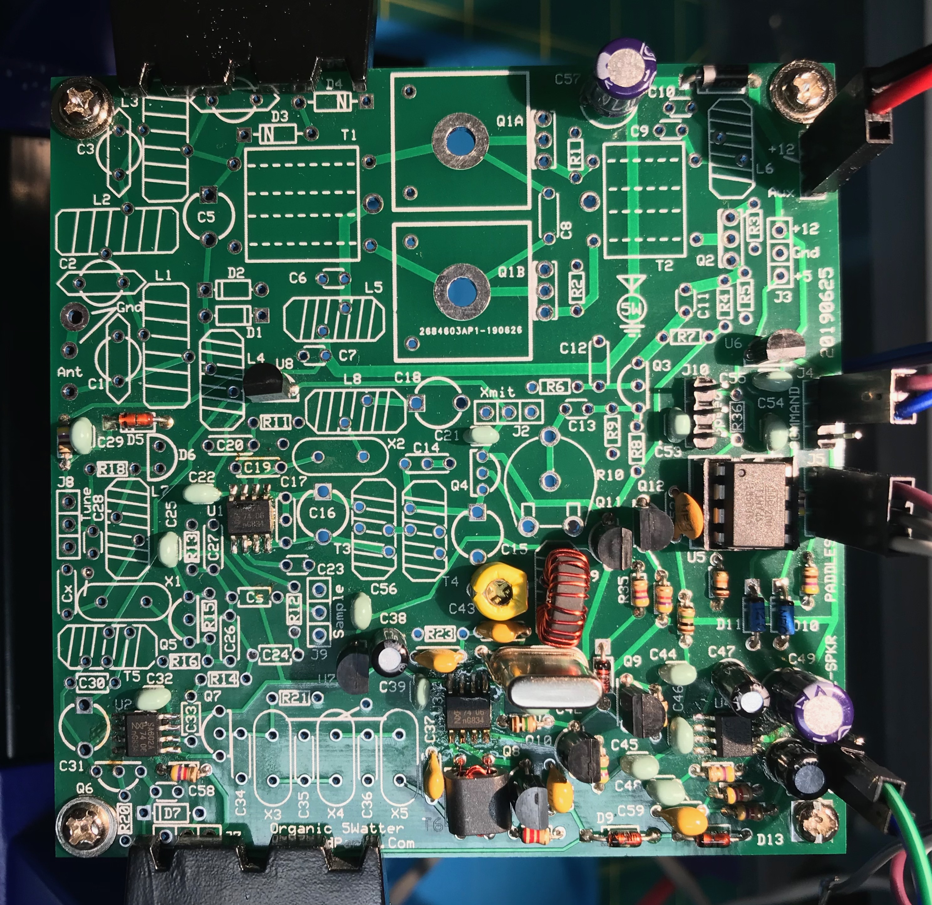
This post is a continuation in the series documenting my build of the 5 Watter Organic VCXO Transceiver.
BFO Build Notes
Chuck’s notes mention that he accidently skipped this section and came back to it. Therefore, pictures included parts we haven’t installed yet.
When installing C43, the flat side goes to the square pad.
Go to section 10 of the kit (W8DIZ) instructions for lengths and kinds of wire to use for each toroid.
I went back and reread Chapter 1, the overview in the K7QO guide. It was then that I realized that the stages we are building in correspond to the block diagram on page 17.
When winding the binoculor T6, I did a quick tin of the ends on the 2 turn wire so I could keep them identified when I wound them. Failure to strip enamel off of wire is a very common failure. I use sand paper to do a rough removal before stripping/tinning the wire. After soldering into place, check for continuity with a meter.
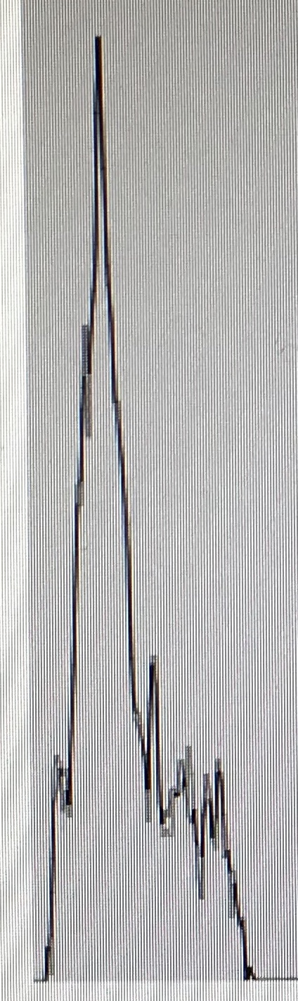
During the testing, I set my function generator up for 8.064Mhz and a sine wave output. See my workbench for specifics.
I connected the audio output of the 5 Watter to my computer running the spectrum analyzer.
First, I configured the analyzer with the built in tone generator and set it for 600Hz. Then, I adjusted the display so that I would have a reference point for where the 600Hz peak was being displayed. Next, turned on the output of the function generator (to a dummy load with a bit of wire coming off of it). I then adjusted C43 so that the pitch heard and displayed matched up to what I was see with the earlier 600Hz setting. I am sure this is all pre-emptive as the real calibration will happen later in this project.
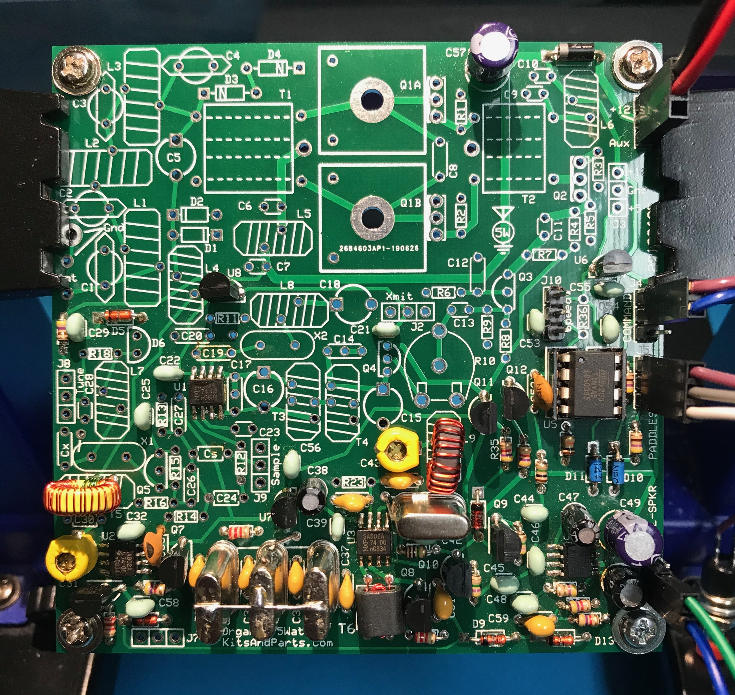
RF Gain, First RX Mixer, IF Amp, and Crystal Filter
I checked my crystals with a K7QO crystal checker before installing them.
Pay attention to the instructions about grounding the cases of the crystals X3, X4, X5
The second winding on T5 is a bit counterintuitive. You will wind it the same way you wound the first winding. Check the pictures in the guide and the instructions section 8.2.
Testing, touch C30 with test wire, will get louder audio
To clean enamel:
Sand paper
Scrape with hobby knife
Run hot solder blob over it
Alternate approach to counting turns is to wind a bunch of turns and then check actual inductance against expected value. There is toroid information and a calculator at kitsandparts.com you can use to determine the target inductance.
I recently had my Elecraft K2 open doing some work on it. I thought I would take the opportunity to align the KAF2. I don’t have a spectrum analyzer. However, I was able to use a browser based audio spectrum analyzer. I connected the output of the K2 to the microphone in line of the station computer.
I used this browser based Sound Spectrum Analyzer to do the alignment. You will need to allow it to use your microphone.
Start with the KAF2 set to OFF. Preamp OFF and Attenuator OFF. Antenna, disconnected. RF Gain fully clockwise and AF Gain adjusted to register on spectrum display. Select widest filter option. S1 should be set to IN position.
In order to do the alignment properly, you need to be zero beat on a signal. I tuned the K2 to the birdy at 7Mhz. Then I activated the spot feature. I could clearly see 2 peaks on the spectrum analyzer. I carefully adjusted the VFO so that there was only 1 peak.
Spectrum Analysis with KAF2 turned offNotice all of the noise to the left of the peak.
Alignment
Consult the Elecraft KAF2 manual. Make sure you have your filter configured for the two stage option. Check jumper W1. It should be open. Also, note that there are two pots on the filter to adjust. Turn the first stage of the KAF2 filter on (AF1). Adjust the R1 pot to peak the output.
KAF2 filter first stage tunedNote the dramatic drop in noise above the peak.
Enable the second stage of the filter (AF2).
KAF2 filter second stage tuned
After adjusting the second stage (with R2) the peak is even more pronounced than before.
There is some interaction between the stages. Alternate between adjusting the first and second stage until you are satisfied that it is calibrated for peak performance. The Elecraft manual suggests doing the BFO and filter cap setup CAL FIL at this time.
5 Watter Phase 3
2 min |
Bryan Nehl |
2020-10-08T00:35
About
This post is a continuation in the series documenting my build of the 5 Watter Organic VCXO Transceiver.
Build Notes
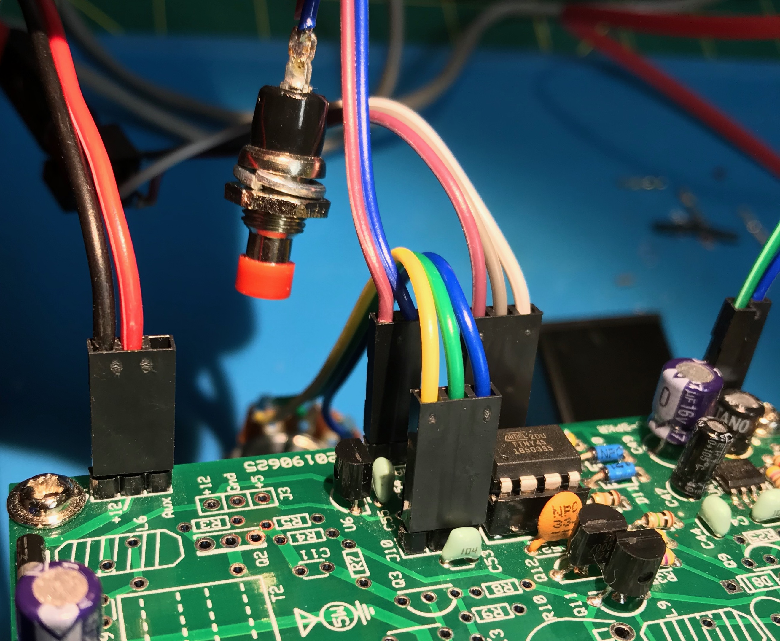
In Phase 3 we are installing the keyer and keying interface sections.
I would also suggest that you solder R33 in place before J5. R33 sits between J5 and the socket for U5.
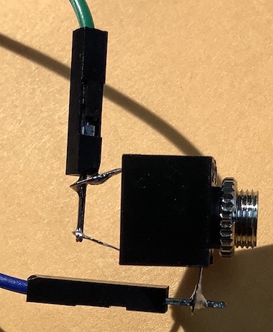
It is up to the builder to decide if they will hardwire directly to J4 and J5, or install Dupont headers. I opted to install Dupont headers. J4 is used for the command button. You’ll need this during the test phase. I wired the 2 pins next to the J4 designator to a momentary button. J5 is a 3 pin header. Ground is in the middle pin. Connect J5 to a “stereo” or TRS 3.5mm jack.
Refer to section 15 Connections, of the standard kitsandparts.com 5 watter building instructions for guidance on wiring up the jacks and pots.
During the testing of Phase 3, I discovered, that an “optional” 10K linear pot will be needed for the Morse Code speed control.
Cut the wire bundles that come with the mounting hardware in half. You’ll wire these to your connectors. You’re still going to need more wire for the speed pot and the DC jack. I found that having the proper crimp tool made working with the dupont connectors much easier. I ordered one of these Dupont crimping tool kits. The kit also contained extra wire which I’ve used right away.
The crimper is listed on My Workbench Page along with the other tools on my workbench.
Cases
I have started researching cases. This is the top enclosure contender at the moment. But I haven’t come to any decision yet.
Frequency Display
The tech group I am a part of is leaning towards adding a QRP Guys Digital Dial to our project.
However, I discovered that in July Chuck did an independent video series building a 17m version. I created a K7QO 5 Watter playlist on YouTube.
Little Dixie Lake Conservation Area POTA K-5706 activation
1 min |
Bryan Nehl |
2020-05-20T02:48
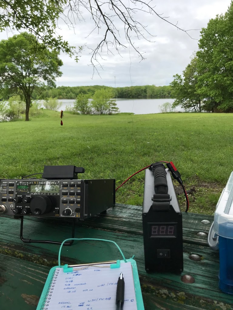
I was lucky enough to be able to get out the morning of May 15th, 2020 and activate Little Dixie Lake Conservation Area in Missouri.
5 Watter Phase 2
1 min |
Bryan Nehl |
2020-05-11T02:00
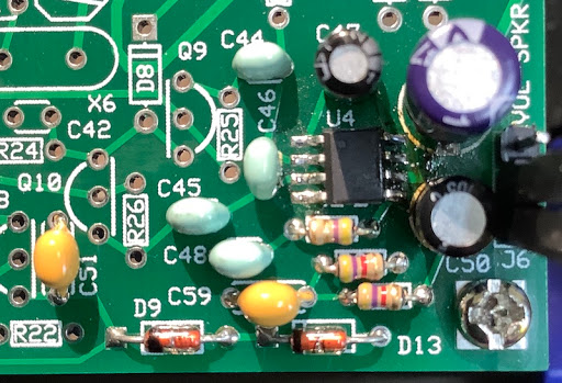
Pay attention to the color stripes/values of the resistors. The colors of the resistors in the K7QO guide did not match with what was expected. In particular, pay attention to R30 and 31, 4K7 resistors – yellow, purple, red, gold color markings.
Don’t forget to read the captions along with the pictures in the guide. The part type for C51 and C59 is different than pictured and noted.
My system current draw at this phase measured 22mA. During the test phase, I was able to use a small breadboard jumper wire to hear amplified audio.
I used female-male breadboard jumpers to temporarily connect the headphone jack.
Then used an amplified speaker for testing.
5 Watter Phase I
3 min |
Bryan Nehl |
2020-05-02T23:22
Parts
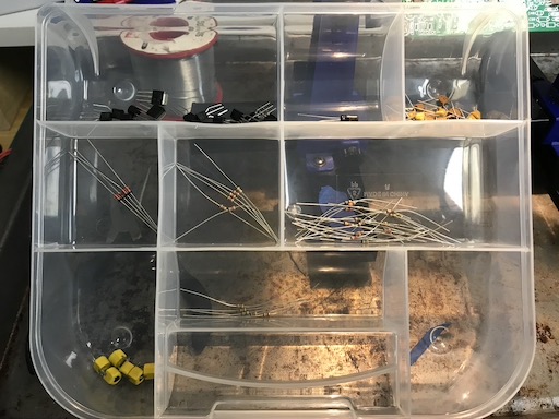
READ instructions before dumping out all of the parts. Several parts are nearly identical and will be extremely difficult to differentiate if you don’t follow the kit instructions. You can inventory and bin some of the components to make your life easier.
We noticed the substitution of SA602 for NE612. There are no dots on the chips to indicate pin 1. We hope, that the NXP logo is in the position of the dot. The data sheet didn’t really enlighten us on this point. Subsequent testing confirmed that the NXP logo is in the position of the dot.
SMD
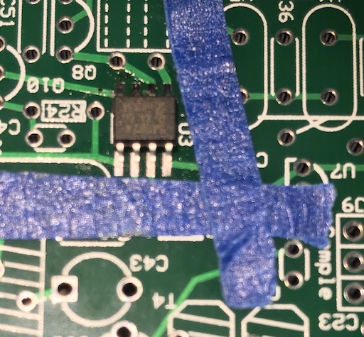
Install the SMD parts first. The part density is high and it would be extremely difficult to add them later. If you are not familiar with SMD soldering there are several approaches/techniques. Techniques include: hot plate, oven, hot air tool, drag soldering, and solder paste. SMD devices can be difficult to see and work with. Good light, a magnification setup of some kind, and a good soldering station are necessities. When using a soldering iron, choice of tip will depend on technique used and user preference. You will also likely use a different tip for SMD work than your regular soldering. I was finding that with the board parts density, I was inadvertently soldering neighboring vias when soldering the SMDs. I cut small strips of painters tape to protect neighboring vias. Doing other work, I had heard of using aluminum foil to protect nearby components. I used a Kester flux pen on the board before putting on the SMD. You may choose to use paste/gel, etc.
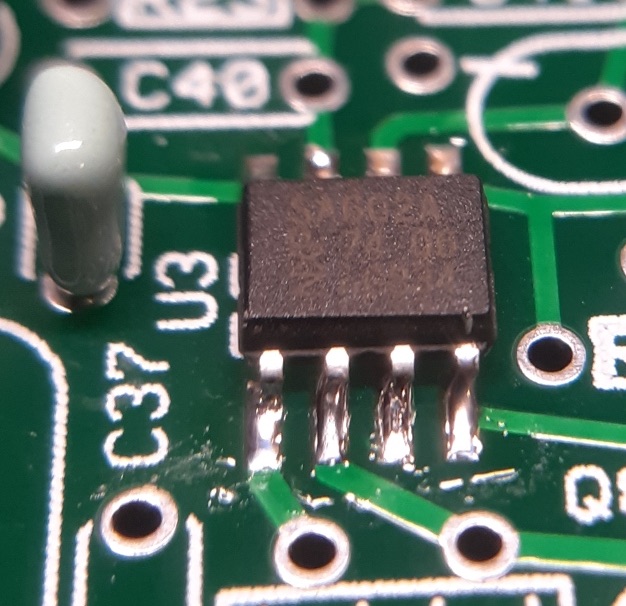
Installed device - W0ODJ
Assembly
There are some minor differences between the K7QO assembly guide and the website instructions. The board and parts have had some minor updates since the guide was created. Keep the original instructions handy during the build too. They include the color codes for the resistors. The assembly guide includes a tip to use some stand offs or bolts/nuts in the corners of the board to keep it above your work surface. Use a board holder as long as you can to make for a more pleasant build process.
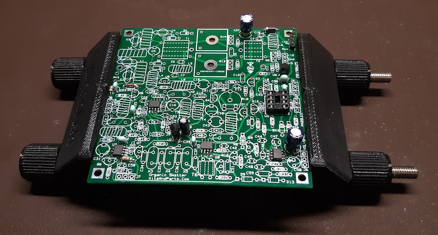
W0ODJ’s completed Phase 1 in board holder
Having a current limited power supply comes in very handy when testing. I picked up one from Amazon. It is nice to be able to ramp up voltage. Also, the current limiting feature may keep you from setting some smoke free. A good digital multi-meter is good to have. I have an old Fluke 8010a I picked up from eBay for around $40. Having some bread board jumpers (female-male) that you can use with the header blocks is handy come test time.
In order to deepen our understanding of amateur radio electronics the tech builder group I am a member of decided to build the 5 Watter QRP rig.
Eagle Bluffs Conservation Area POTA activation K-6524
1 min |
Bryan Nehl |
2020-03-28T18:43
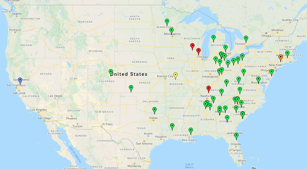
K-6524 at Yellow pin, Green Pins 40m phone, Red pins 75m phone, Blue pin 20m phone, Orange pin 30m CW. One nearby 2m FM simplex contact not visible on map.
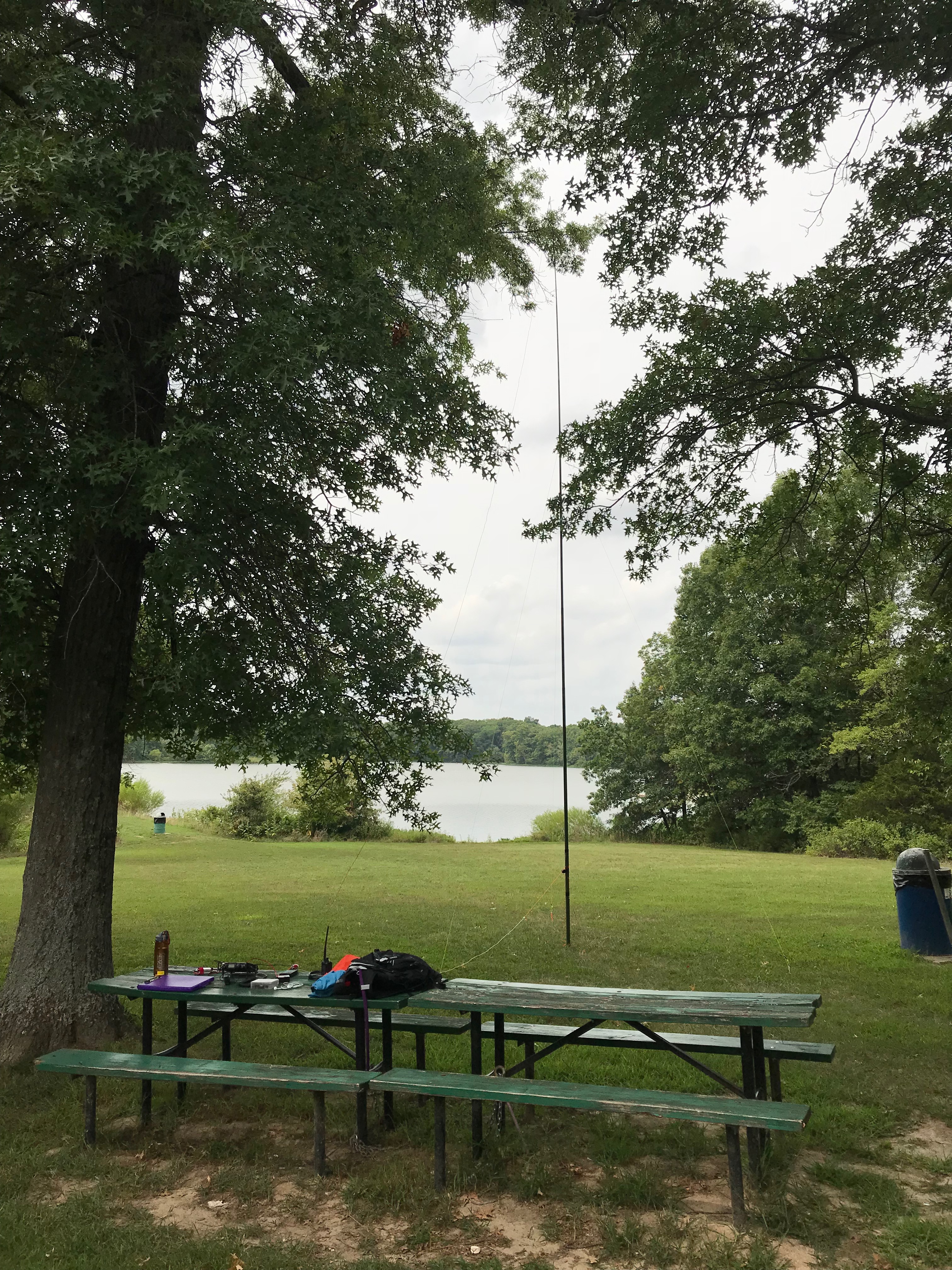
Rick KC0PET, Ted KC0RDM and I, K0EMT set up at Little Dixie Lake CA in Calloway County. Initially we checked in at the main boat ramp area. It had a nice pavilion. But, we felt we might be able to do better. So, we went to the disabled accessible trail area. There we found several picnic tables, grills, shade trees and plenty of open field. That
QRPTTF 2018
1 min |
Bryan Nehl |
2018-04-27T01:15
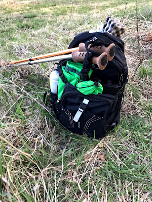
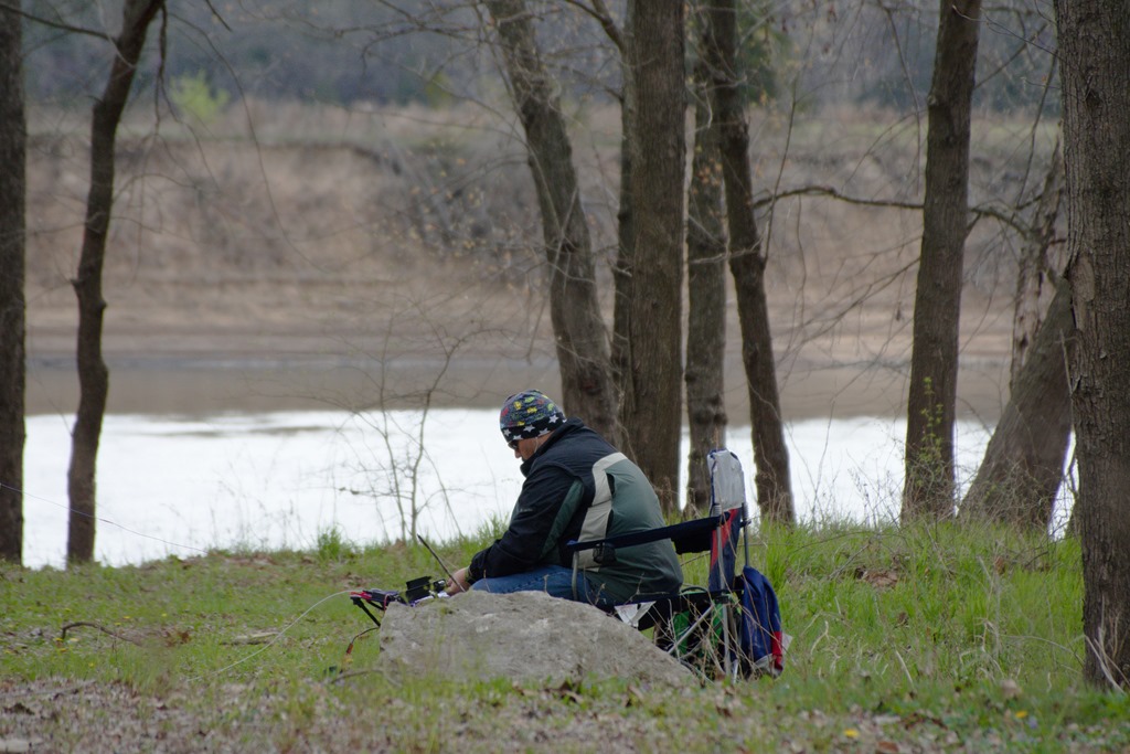
The QRP to the field 2018 event had a river theme going this year. So, Ted, KC0RDM and I, Bryan, K0EMT headed to the Osage River and set up at Pikes Camp Access. It was a chilly morning. I was wearing multiple layers and a hat. After noon though it warmed up into the low 60s with a chilly wind.
Conditions were very tough this year. I only got three contacts. Two with Morse code, one with SSB. Although, I was tickled that one was with Paul, NA5N. I was able to hear quite a few stations. Just didn